Neurotrophic electrode: method of assembly and implantation into human motor speech cortex
- PMID: 18672003
- PMCID: PMC2574508
- DOI: 10.1016/j.jneumeth.2008.06.030
Neurotrophic electrode: method of assembly and implantation into human motor speech cortex
Abstract
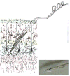
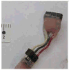
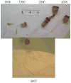
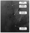
The neurotrophic electrode (NE) is designed for longevity and stability of recorded signals. To achieve this aim it induces neurites to grow through its glass tip, thus anchoring it in neuropil. The glass tip contains insulated gold wires for recording the activity of the myelinated neurites that grow into the tip. Neural signals inside the tip are electrically insulated from surrounding neural activity by the glass. The most recent version of the electrode has four wires inside its tip to maximize the number of discriminable signals recorded from ingrown neurites, and has a miniature connector. Flexible coiled, insulated gold wires connect to electronics on the skull that remain subcutaneous. The implanted electronics consist of differential amplifiers, FM transmitters, and a sine wave at power up for tuning and calibration. Inclusion criteria for selecting locked-in subjects include medical stability, normal cognition, and strong caregiver support. The implant target is localized via an fMRI-naming task. Final localization at surgery is achieved by 3D stereotaxic localization. During recording, implanted electronics are powered by magnetic induction across an air gap. Coiled antennas placed on the scalp over the implanted transmitters receive the amplified FM transmitter outputs. Data is processed as described elsewhere where stability and longevity issues are addressed. Five subjects have been successfully implanted with the NE. Recorded signals persisted for over 4 years in two subjects who died from underlying illnesses, and continue for over 3 years in our present subject.
Figures


References
-
- Andersen RA, Buneo CA. Intentional maps in posterior parietal cortex. Annual Rev Neurosci. 2002;25:189–220. - PubMed
-
- Kennedy PR. A long-term electrode that records from neurites grown onto its recording surface. J Neuroscience Methods. 1989;29:181–93. - PubMed
-
- Kennedy PR. Comparing electrodes for use as cortical control signals: Tiny tines, tiny wires or tiny cones on wires: Which is best? In: Brazino Joe., editor. The Biomedical Engineering Handbook. Third. 2006. pp. 32.1–32.14.
-
- Kennedy PR, Andreasen D, Ehirim P, King B, Kirby T, Mao H, Moore M. Using human extra-cortical local field potentials to control a switch. J Neural Eng. 2004;1:72–7. - PubMed
MeSH terms
Grants and funding
LinkOut - more resources
Full Text Sources
Other Literature Sources
Medical
Miscellaneous

