. 2008 Aug 6;16(8):1267-74.
doi: 10.1016/j.str.2008.05.010.

Defining molecular and domain boundaries in the bacteriophage phi29 DNA packaging motor

Affiliations

Defining molecular and domain boundaries in the bacteriophage phi29 DNA packaging motor

Marc C Morais et al. Structure. .

Abstract

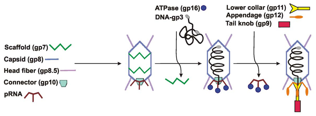
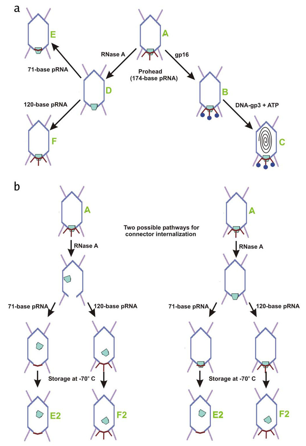
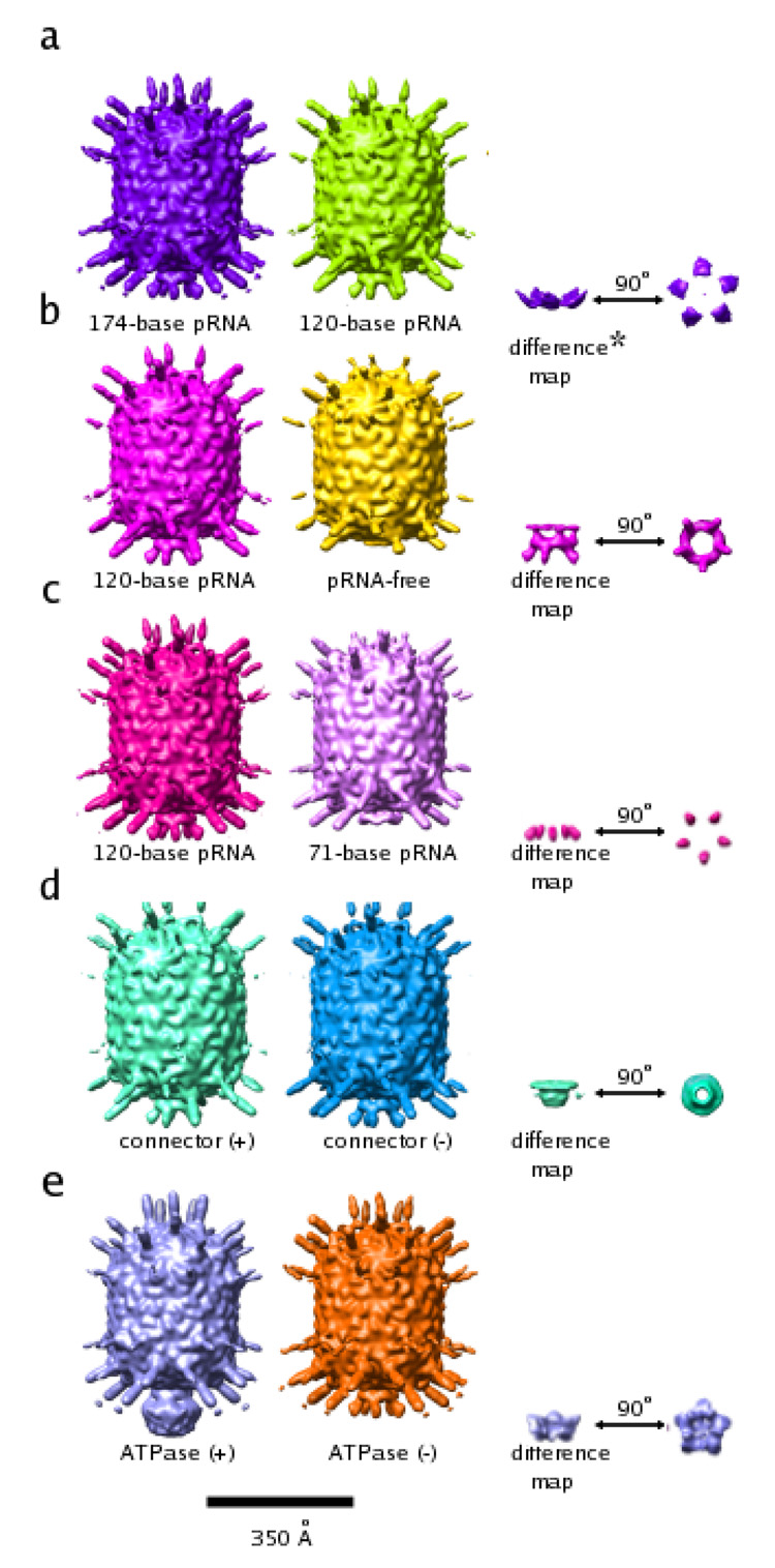
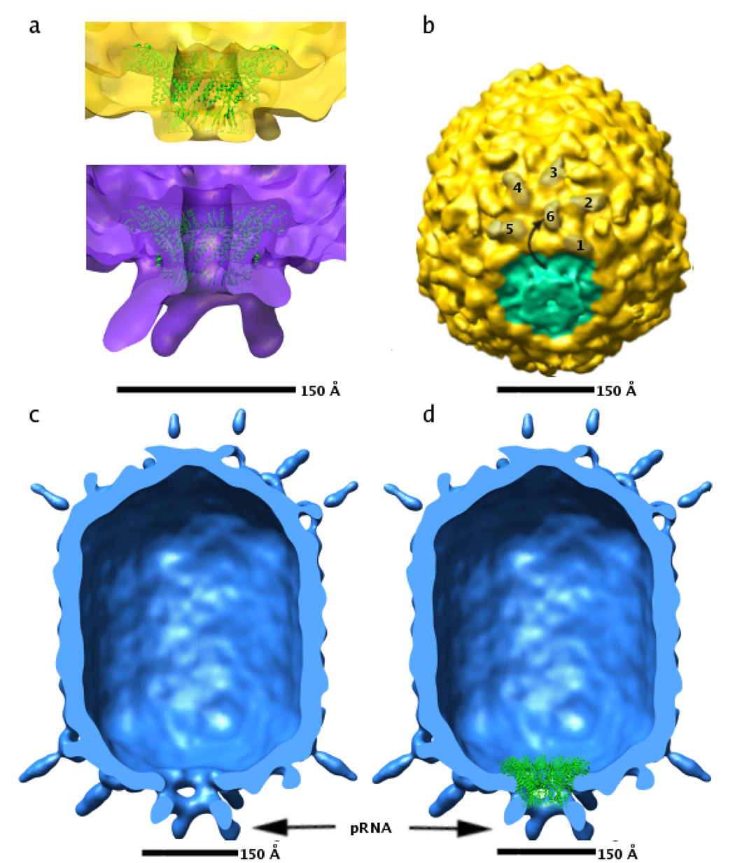
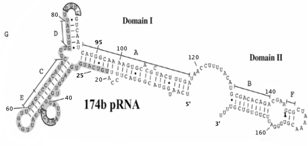
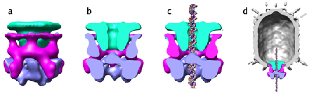
Cryo-electron microscopy (cryo-EM) studies of the bacteriophage phi29 DNA packaging motor have delineated the relative positions and molecular boundaries of the 12-fold symmetric head-tail connector, the 5-fold symmetric prohead RNA (pRNA), the ATPase that provides the energy for packaging, and the procapsid. Reconstructions, assuming 5-fold symmetry, were determined for proheads with 174-base, 120-base, and 71-base pRNA; proheads lacking pRNA; proheads with ATPase bound; and proheads in which the packaging motor was missing the connector. These structures are consistent with pRNA and ATPase forming a pentameric motor component around the unique vertex of proheads. They suggest an assembly pathway for the packaging motor and a mechanism for DNA translocation into empty proheads.


Figures

Figure 1
Figure 1. Assembly pathway of bacteriophage ϕ29
Various phage proteins are shown schematically, with the names of the proteins written next to their schematic representations.
Figure 2
Figure 2. Diagram of particle production
Phage proteins are colored as in Figure 1. Different particles are identified as A – F (green text). (A) Production of all particles which retained the connector. (B) Two possible pathways, both beginning with particle A, for the formation of connector-internalized particles (E2 and F2). The two pathways differ only in which step connectors are displaced.
Figure 3
Figure 3. Reconstructions of ϕ29 proheads
All reconstructions are shown as surface-shaded renderings contoured at 1.5 standard deviations above the mean of the map. A short description is written below each particle. Although Figures 3A (middle), B (left), C (left), and D (left) all show the same reconstruction, they are colored differently. As a consequence, the resultant structural features in the difference maps come out in different colors. The color of the difference densities are maintained in all figures shown in this paper. (A) Prohead with 174-base pRNA (left), prohead with 120-base pRNA (middle), difference map between the two (right; side view (near right), end-on view (far right)). (B) Prohead with 120-base pRNA plus connector (left), pRNA-free prohead (middle), difference map between the two (right; side view (near right), end-on view (far right)). (C) Prohead with 120-base pRNA plus connector (left, same reconstruction as in a), shown again to clarify the difference map shown on the right), prohead with 71-base pRNA plus connector (middle), difference map between the two (right; side view (near right), end-on view (far right)). (D) Prohead with 120-base pRNA plus connector (left same reconstruction as in a) and b), shown again to clarify difference map shown on the right), connector internalized prohead (middle), difference map between the two (right; side view (near right), end-on view (far right)). (E) Prohead with 174-base pRNA plus connector (middle) and the same prohead with bound ATPase (left), difference between the two (right; side view (near right), end- on view (far right)). * The asterisk indicates that the feature shown is contoured at less than 0.1 standard deviations above the mean electron density value of the map. Additional noise features also visible at this contour level were masked out manually so that the feature in question would be visible in the figure.
Figure 4
Figure 4. CryoEM reconstructions of pRNA-free and connector-free particles
(A) Fit of the atomic coordinates of the connector (green ribbon, Protein Data Bank accession code 1IJG) to density corresponding to the connector in pRNA-free proheads (top, yellow density) and to 174-base proheads (bottom, purple density). (B) Skewed view of pRNA-free particle showing rotation of the BIG II domain in capsid proteins abutting the connector. Six BIG II domains in one of the five hexamers surrounding the connector are shaded brown, and numbered 1–6. The ~180 degree rotation of the BIG2 domain labeled six is indicated by a curved arrow. Approximate density corresponding to the connector is shaded green. (C) Cut-away view of connector internalized particle with the front half of the particle removed. (D) Same as (C), but with the atomic coordinates of the connector (shown as green ribbon) placed according to their fit to wild-type cryoEM density maps. Density corresponding to the pRNA in panels (C) and (D) is indicated by a black arrow.
Figure 5
Figure 5. Secondary structure and domain prediction for pRNA
Domains I and II are indicated. Base paired helices are labeled A through G. Bases believed to be involved in prohead binding are boxed in gray. Every 20th residue is labeled and residues 25 and 95, the residues that mark the ends of the 71 base pRNA are marked in bold font. The 3’ and 5’ ends of the 174-base pRNA are also marked in bold font.
Figure 6
Figure 6. Combination of difference maps
Density from difference maps (Figure 3) isolating the connector (green), pRNA (magenta) and ATPase (blue) were combined to visualize the DNA packaging motor in ϕ29. (A) End-on view of the motor, looking from the pRNA down the long axis of the phage. (B), Cut-away of side view of the motor, with the front half of the motor density removed. (C) Cut-away of side view of the motor, with the front half of the motor density removed and the structure of DNA placed in the central channel of the packaging motor. (D).The motor is shown in the context of the entire prohead. The front half of the prohead density has been removed so all the motor components can be seen.

References

    1. Anderson D, Reilly B. Morphogenesis of bacteriophage ϕ29. In: Sonenshein AL, Hoch JA, Losick R, editors. Bacillus subtilis and Other Gram-Positive Bacteria: Biochemistry, Physiology, and Molecular Genetics. Washington, D.C.: American Society for Microbiology; 1993. pp. 859–867.
    1. Atz R, Ma S, Gao J, Anderson DL, Grimes S. Alanine Scanning and Fe-BABE probing of the bacteriophage ϕ29 prohead RNA connector interaction. J. Mol. Biol. 2007;369:239–248. - PMC - PubMed
    1. Bailey S, Wichitwechkarn J, Johnson D, Reilly BE, Anderson DL, Bodley JW. Phylogenetic analysis and secondary structure of the Bacillus subtilis bacteriophage RNA required for DNA packaging. J. Biol. Chem. 1990;265:22365–22370. - PubMed
    1. Baumann RG, Mullaney J, Black LW. Portal fusion protein constraints on function in DNA packaging of bacteriophage T4. Mol. Microbiol. 2006;61:16–32. - PubMed
    1. Bazinet C, King J. The DNA translocating vertex of dsDNA bacteriophage. Annu. Rev. Microbiol. 1985;39:109–129. - PubMed

Publication types

LinkOut - more resources