. 2008 Aug 22;134(4):646-56.
doi: 10.1016/j.cell.2008.06.026.

Opposing Wnt pathways orient cell polarity during organogenesis

Affiliations

Opposing Wnt pathways orient cell polarity during organogenesis

Jennifer L Green et al. Cell. .

Abstract

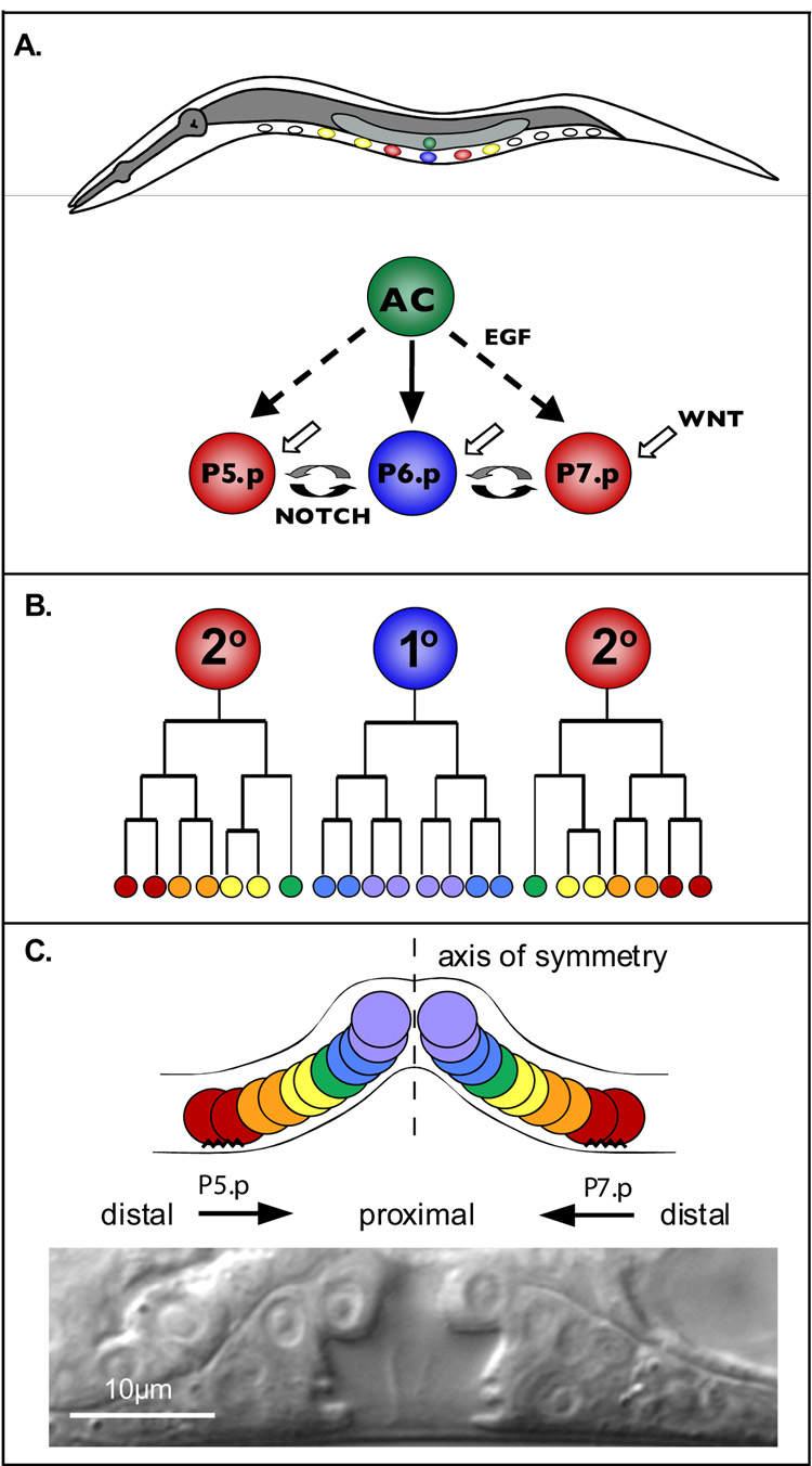
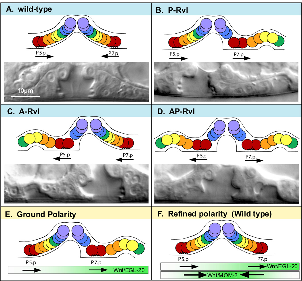
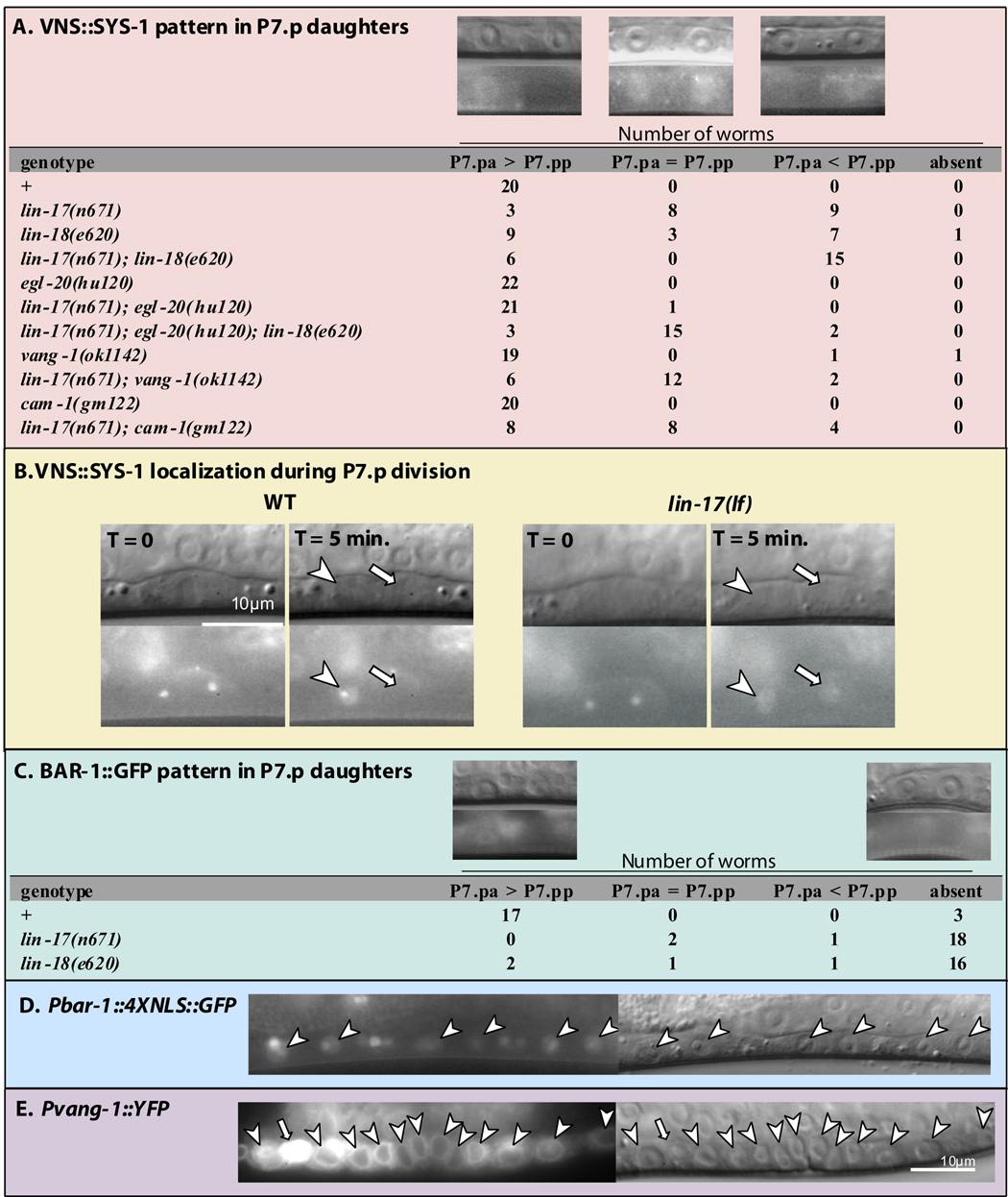
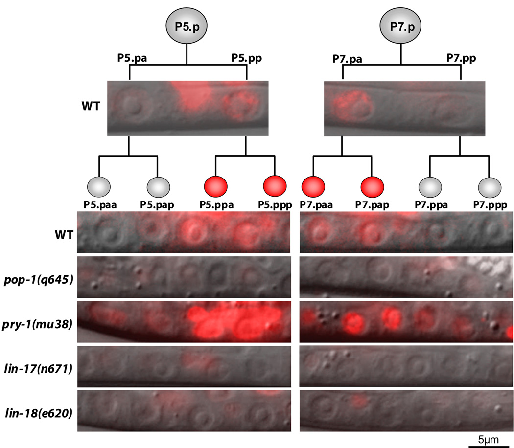
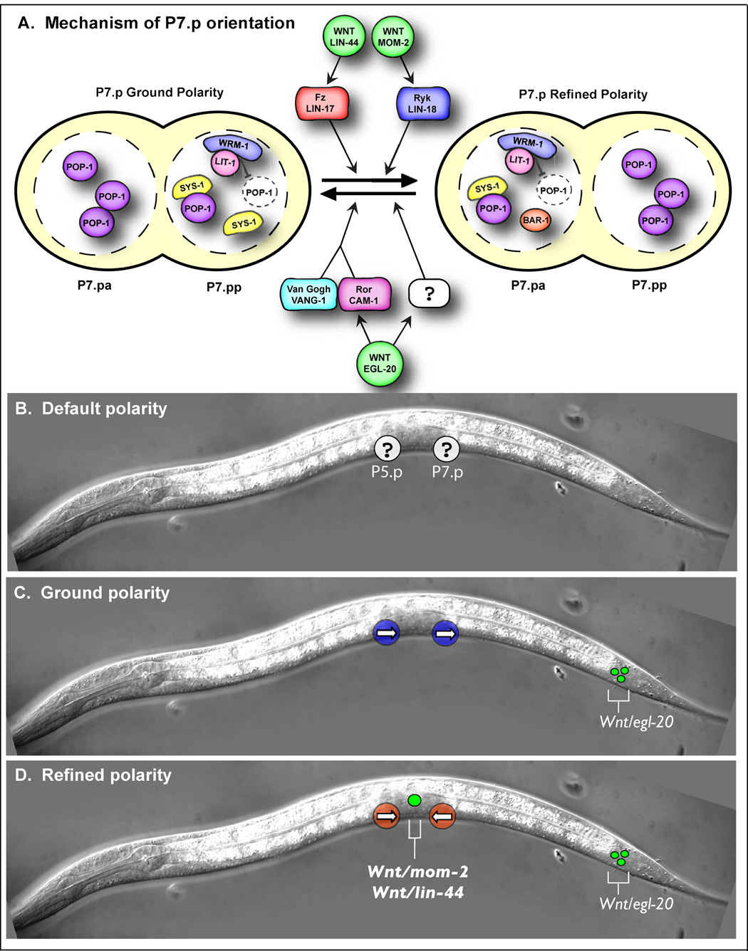
The orientation of asymmetric cell division contributes to the organization of cells within a tissue or organ. For example, mirror-image symmetry of the C. elegans vulva is achieved by the opposite division orientation of the vulval precursor cells (VPCs) flanking the axis of symmetry. We characterized the molecular mechanisms contributing to this division pattern. Wnts MOM-2 and LIN-44 are expressed at the axis of symmetry and orient the VPCs toward the center. These Wnts act via Fz/LIN-17 and Ryk/LIN-18, which control beta-catenin localization and activate gene transcription. In addition, VPCs on both sides of the axis of symmetry possess a uniform underlying "ground" polarity, established by the instructive activity of Wnt/EGL-20. EGL-20 establishes ground polarity via a novel type of signaling involving the Ror receptor tyrosine kinase CAM-1 and the planar cell polarity component Van Gogh/VANG-1. Thus, tissue polarity is determined by the integration of multiple Wnt pathways.


Figures

Figure 1
Figure 1. C. elegans vulva development
A) Schematic of vulval induction; anterior—left, dorsal—up. B) Lineage trees of the VPC progeny, P5.p—left, P6.p—center, P7.p—right. C) Schematic arrangement (top) of the 1° and 2° vulval lineages along a proximal-distal axis. The cells located anterior or posterior to the axis of symmetry (dashed line) display opposite orientations. The jagged lines represent adherence to the cuticle. At the bottom is a Nomarski image of a wild-type vulva at the L4 stage.
Figure 2
Figure 2. Vulval lineage orientations and layered polarity model
Schematic arrangements of vulval lineages (top) and an example Nomarski image (bottom) for the four possible orientation combinations of P5.p and P7.p. Anterior-left. A) Wild-type, P5.p faces posteriorly and P7.p faces anteriorly. B) P-Rvl, both P5.p and P7.p face posteriorly. C) A-Rvl, both P5.p and P7.p face anteriorly. D) AP-Rvl, P5.p faces anteriorly and P7.p faces posteriorly. E) EGL-20, expressed from the posterior, promotes both P5.p and P7.p to face posteriorly. F) MOM-2, expressed in the centrally located anchor cell, orients both P5.p and P7.p toward the center. MOM-2 reverses P7.p polarity so that it faces anteriorly and reinforces the posterior-facing orientation of P5.p.
Figure 3
Figure 3. SYS-1, BAR-1, and VANG-1 expression in VPC progeny
A) Subcellular localization of qIs95, a VNS∷SYS-1 translational fusion. qIs95 is expressed at very low levels. To characterize the localization, we captured a still fluorescence image using a long exposure time (8 sec.) and then applied the “Auto Contrast” function of Adobe Photoshop CS2. The resulting localization pattern was readily classifiable by eye into one of the three categories: SYS-1 was enriched in the anterior P7.p daughter nucleus (P7.pa > P7.pp), SYS-1 was present at similar levels in both P7.p daughter nuclei (P7.pa = P7.pp), or SYS-1 was enriched in the posterior P7.p daughter nucleus (P7.pa < P7.pp). A representative image is shown above each category and the number of worms in each category is listed. The VNS∷SYS-1 localization pattern in P5.p daughters was unaffected in all of the genotypes examined, with the exception of symmetric distribution in a single lin-17(lf); egl-20(lf) double mutant worm and in two lin-17(lf); egl-20(lf); lin-18(lf) triple mutants. B) Nomarski (above) and fluorescence images (below) show VNS∷SYS-1 localization during cell division. For wild type and lin-17(lf) mutants, the images on the right were taken 5 minutes after the images on the left. The two spots seen in the fluorescent images on the left are putative centrosomes. Arrowheads point to anterior daughter nuclei and arrows point to posterior daughter nuclei. C) BAR-1∷GFP translation fusion; display is the same as in (A). D) A bar-1∷GFP reporter that contains 5.1 kb of the bar-1 5’ regulatory region driving expression of nucleolus/nuclear localized GFP. This promoter region is the same as in panel C (Eisenmann et al., 1998). E) vang-1∷YFP reporter is expressed in the VPC progeny (arrowheads). The bright vang-1∷YFP expressing cell (arrow) is a ventral cord neuron.
Figure 4
Figure 4. POPTOP expression in VPC granddaughters
Overlay of Nomarski and fluorescence (red) images showing POPTOP expression in the VPC progeny. Representative images are shown. Fluorescent images of the VPC granddaughters were each exposed for 1 second, except for pry-1(mu38), which was exposed for 0.5 seconds. The fluorescence remaining in lin-17(lf) and lin-18(lf) mutants is in ventral cord neurons, where POPTOP is also expressed.
Figure 5
Figure 5. Model of VPC orientation
A) Illustration of the genetic interactions contributing to the orientation of P7.p and the nuclear localization of POP-1, WRM-1, LIT-1, SYS-1, and BAR-1 in ground and refined polarity. We have examined WRM-1 and LIT-1 localization in refined polarity, but WRM-1 and LIT-1 localization in ground polarity is inferred from POP-1 localization, which was previously described (Deshpande et al., 2005). Localization of SYS-1 and BAR-1 in ground and refined polarity was described here. B—D) Schematics of default, ground, and refined polarity. B) In the absence of Wnts, the orientation of P5.p and P7.p (white circles) is random (represented by a question mark). C) egl-20/Wnt is expressed in the tail (green circles) and establishes ground polarity in which both P5.p and P7.p (blue circles) face posteriorly (arrows). D) Wnts mom-2 and lin-44 are expressed in the AC (big green circle) and instruct P5.p and P7.p (red circles) to face the center (arrows).
Figure 6
Figure 6. ROR/CAM-1 structure and molecular lesions of mutations
CAM-1 protein structure depicting Ig (Immunoglobulin) domain, CRD (cysteine-rich domain), Kr (kringle domain), TM (transmembrane) domain, kinase domain, and S/T (serine/threonine-rich) domain. Amino terminus is to the left. The molecular nature of cam-1 mutant alleles is given below.

References

    1. Baena-Lopez LA, Baonza A, Garcia-Bellido A. The orientation of cell divisions determines the shape of Drosophila organs. Curr Biol. 2005;15:1640–1644. - PubMed
    1. Brenner S. The genetics of Caenorhabditis elegans. Genetics. 1974;77:71–94. - PMC - PubMed
    1. Coudreuse DY, Roel G, Betist MC, Destree O, Korswagen HC. Wnt gradient formation requires retromer function in Wnt-producing cells. Science. 2006;312:921–924. - PubMed
    1. Deans MR, Antic D, Suyama K, Scott MP, Axelrod JD, Goodrich LV. Asymmetric distribution of prickle-like 2 reveals an early underlying polarization of vestibular sensory epithelia in the inner ear. J Neurosci. 2007;27:3139–3147. - PMC - PubMed
    1. Deshpande R, Inoue T, Priess JR, Hill RJ. lin-17/Frizzled and lin-18 regulate POP-1/TCF-1 localization and cell type specification during C. elegans vulval development. Dev Biol. 2005;278:118–129. - PubMed

Publication types