

Mechanical imaging of the breast
- PMID: 18753043
- PMCID: PMC2581459
- DOI: 10.1109/TMI.2008.922192
Mechanical imaging of the breast
Abstract
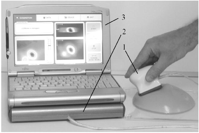
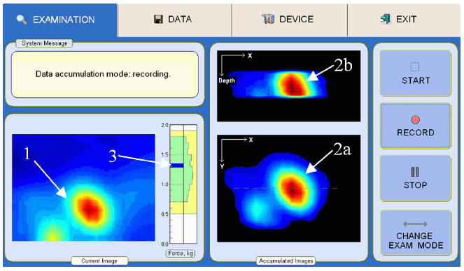
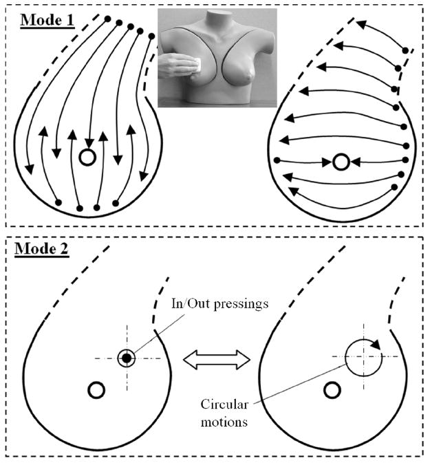
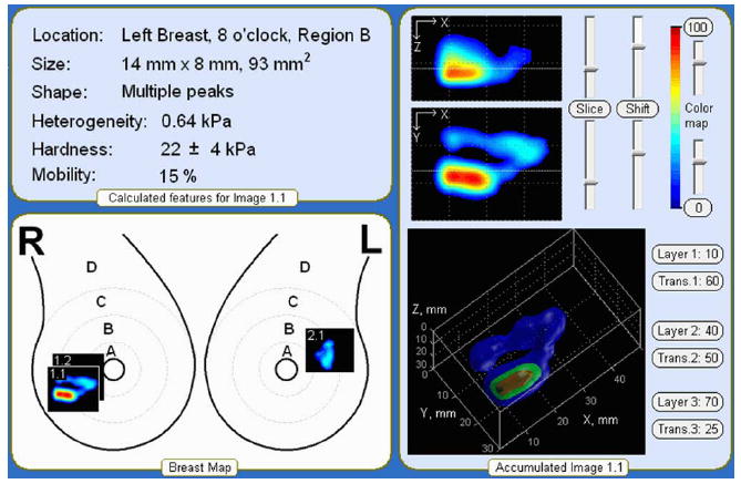
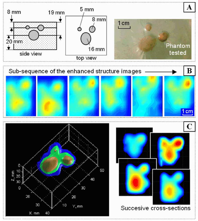
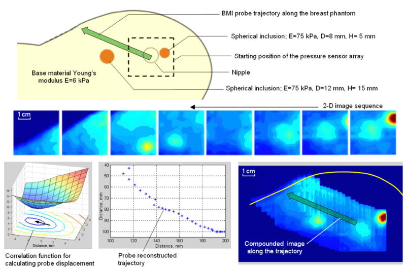
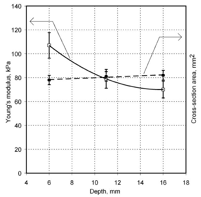
In this paper, we analyze the physical basis for elasticity imaging of the breast by measuring breast skin stress patterns that result from a force sensor array pressed against the breast tissue. Temporal and spatial changes in the stress pattern allow detection of internal structures with different elastic properties and assessment of geometrical and mechanical parameters of these structures. The method entitled mechanical imaging is implemented in the breast mechanical imager (BMI), a compact device consisting of a hand held probe equipped with a pressure sensor array, a compact electronic unit, and a touchscreen laptop computer. Data acquired by the BMI allows calculation of size, shape, consistency/hardness, and mobility of detected lesions. The BMI prototype has been validated in laboratory experiments on tissue models and in an ongoing clinical study. The obtained results prove that the BMI has potential to become a screening and diagnostic tool that could largely supplant clinical breast examination through its higher sensitivity, quantitative record storage, ease-of-use, and inherent low cost.
Figures
Similar articles
-
Differentiation of benign and malignant breast lesions by mechanical imaging.Breast Cancer Res Treat. 2009 Nov;118(1):67-80. doi: 10.1007/s10549-009-0369-2. Epub 2009 Mar 21. Breast Cancer Res Treat. 2009. PMID: 19306059 Free PMC article. Clinical Trial.
-
Prostate mechanical imaging: 3-D image composition and feature calculations.IEEE Trans Med Imaging. 2006 Oct;25(10):1329-40. doi: 10.1109/tmi.2006.880667. IEEE Trans Med Imaging. 2006. PMID: 17024836 Free PMC article.
-
A novel deformation method for fast simulation of biological tissue formed by fibers and fluid.Med Image Anal. 2012 Jul;16(5):1038-46. doi: 10.1016/j.media.2012.04.002. Epub 2012 Apr 25. Med Image Anal. 2012. PMID: 22584040
-
Recent technological advancements in breast ultrasound.Ultrasonics. 2016 Aug;70:183-90. doi: 10.1016/j.ultras.2016.04.021. Epub 2016 Apr 25. Ultrasonics. 2016. PMID: 27179143 Review.
-
Selected methods for imaging elastic properties of biological tissues.Annu Rev Biomed Eng. 2003;5:57-78. doi: 10.1146/annurev.bioeng.5.040202.121623. Epub 2003 Apr 10. Annu Rev Biomed Eng. 2003. PMID: 12704084 Review.
Cited by
-
Surface elasticity imaging of vascular tissues in a liquid environment by a scanning haptic microscope.J Artif Organs. 2010 Jul;13(2):121-5. doi: 10.1007/s10047-010-0503-2. Epub 2010 May 15. J Artif Organs. 2010. PMID: 20473627
-
Differentiation of benign and malignant breast lesions by mechanical imaging.Breast Cancer Res Treat. 2009 Nov;118(1):67-80. doi: 10.1007/s10549-009-0369-2. Epub 2009 Mar 21. Breast Cancer Res Treat. 2009. PMID: 19306059 Free PMC article. Clinical Trial.
-
Tactile imaging of an imbedded palpable structure for breast cancer screening.ACS Appl Mater Interfaces. 2014 Sep 24;6(18):16368-74. doi: 10.1021/am5046789. Epub 2014 Aug 29. ACS Appl Mater Interfaces. 2014. PMID: 25148477 Free PMC article.
-
Biomechanical integrity score of the female pelvic floor.Int Urogynecol J. 2022 Jun;33(6):1617-1631. doi: 10.1007/s00192-022-05120-w. Epub 2022 Mar 1. Int Urogynecol J. 2022. PMID: 35230483 Free PMC article.
-
Modern breast cancer detection: a technological review.Int J Biomed Imaging. 2009;2009:902326. doi: 10.1155/2009/902326. Epub 2009 Dec 28. Int J Biomed Imaging. 2009. PMID: 20069109 Free PMC article.
References
-
- Cancer facts & figures 2007. Amer. Cancer. Soc.; Atlanta, GA: p. 6.
-
- Breast cancer facts & figures 2005–2006. Amer. Cancer. Soc.; Atlanta, GA: pp. 1–32.
-
- Berry DA, et al. Effect of screening and adjuvant therapy on mortality from breast Cancer; Cancer intervention and surveillance modeling network (CISNET) collaborators. New Eng J Med. 2005;353:1784–1792. - PubMed
-
- Bevers TB. National Comprehensive Cancer Network, Clinical Practice Guidelines in Oncology. 1. Fort Washington, PA: NCCN; 2006. Breast cancer screening and diagnosis guidelines; pp. 1–38.
-
- Pisano ED, et al. Diagnostic performance of digital versus film mammography for breast-cancer screening. N Engl J Med. 2005;353(17):1773–1883. - PubMed
Publication types
MeSH terms
Grants and funding
LinkOut - more resources
Full Text Sources
Other Literature Sources
