Review
. 2008 Sep;40(5):446-76.
doi: 10.3200/JMBR.40.5.446-476.

Multifinger prehension: an overview

Affiliations
Review

Multifinger prehension: an overview

Vladimir M Zatsiorsky et al. J Mot Behav. 2008 Sep.

Abstract

The authors review the available experimental evidence on what people do when they grasp an object with several digits and then manipulate it. The article includes three parts, each addressing a specific aspect of multifinger prehension. In the first part, the authors discuss manipulation forces (i.e., the resultant force and moment of force exerted on the object) and the digits' contribution to such forces' production. The second part deals with internal forces defined as forces that cancel each other and do not disturb object equilibrium. The authors discuss the role of the internal forces in maintaining the object stability, with respect to such issues as slip prevention, tilt prevention, and resistance to perturbations. The third part is devoted to the motor control of prehension. It covers such topics as prehension synergies, chain effects, the principle of superposition, interfinger connection matrices and reconstruction of neural commands, mechanical advantage of the fingers, and the simultaneous digit adjustment to several mutually reinforcing or conflicting demands.


Figures

Figure 1
Figure 1
Experimental ‘inverted-T’ handle/beam apparatus commonly used to study the prismatic precision grip. Five six-component force sensors (black rectangles) are used to register individual digit forces. During testing the suspended load was varied among the trials. The load displacement along the horizontal bar created torques from 0 N·m to 1.5 N·m in both directions. The torques are in the plane of the grasp. While forces in all three directions were recorded the forces in Z direction were very small and, if not mentioned otherwise, were neglected. When the handle is oriented vertically the force components in the X and Y directions are the normal and shear, (or tangential) forces, respectively. (Reprinted by permission from V.M. Zatsiorsky, F. Gao, and M.L. Latash (2003a) Finger force vectors in multi-finger prehension. J Biomech 36: 1745-1749.)
Figure 2
Figure 2
Representative examples of digit force vectors (A) and displacement of the points of digit force application on the sensor surface (B). The handle (total weight 15.71 N) was maintained vertically at rest in the air at three different torques exerted on the handle, −1.5 Nm, 0 Nm (no torque), and 1.5 Nm. The torques were applied to the handle about an axis perpendicular to the plane of the page. The subjects were instructed to exert minimal force on the handle. The positive and negative direction of the torque refers to the resistive torque exerted by the subject (which is in the opposite direction to the external torque due to the loading). The supination torque efforts are negative and the pronation torque efforts are positive. (A) The thin arrows originating at the five force sensors represent the corresponding digit forces; they are in proportion to force magnitude and along the line of force action. The two thick curved arrows indicate the subject efforts either in supination (−1.5 Nm, the arrow on the left) or in pronation (1.5 Nm, on the right), group average data. In this and future references, if not mentioned otherwise, the sensors are covered by 100-grit sandpaper (friction coefficient ≈ 1.40–1.52). (B) Displacement of the point of application of digit forces in the vertical direction at the various torque levels. The results are for an individual subject (average of ten trials). Note that the displacement can be as large as 10 mm. (Adapted by permission from V.M. Zatsiorsky, F. Gao, and M.L. Latash. Finger force vectors in multi-finger prehension. Journal of Biomechanics, 2003, 36:1745–1749).
Figure 3
Figure 3
Three cardinal planes of the hand. Adapted by permission from Z.-M.Li, M.L. Latash, and V.M. Zatsiorsky (1998a) Force sharing among fingers as a model of the redundancy problem. Experimental Brain Research 119: 276–286.
Figure 4
Figure 4
Total normal force and moment of the normal forces at different thumb locations (averaged across subject values, N; n =10). The experiment included three parts. Part 1: Grip with the thumb at different locations. With the thumb at a specified location, the handle was lifted and gripped maximally. In various trials, the thumb location was changed systematically from the level of the index finger down to the level of the little finger at a 15 mm step. The six data sets at abscissa of 0, 15, 30, 45, 60, and 75 mm are for the six fixed thumb locations. Part 2: Press with the four fingers. The firmly secured handle was oriented vertically. The subjects were asked to press as hard as possible with all four fingers. Part 3. Selection of the comfortable thumb position. The subjects were asked to choose the most convenient thumb position in the prismatic grasps. The vertical dotted line indicates the comfortable thumb location (GCOM). (Adapted by permission from Z.-M. Li, M.L. Latash, K.M. Newell, and V.M. Zatsiorsky Motor redundancy during maximal voluntary contraction in four-finger tasks. Exp Brain Res. 1998b; 122(1):71–77.)
Figure 5
Figure 5
Finger forces in a task of exerting a 4-finger force in a prescribed direction. The angles are in the flexion-extension plane. Visual feedback of the IMRL force was provided. The force polygon is obtained by adding tail-to-head the individual finger forces. Group average data are shown (n =9). Note the large difference in the direction of the index and little finger forces. Reprinted by permission from F. Gao, M.L. Latash, and V.M. Zatsiorsky. Control of finger force direction in the flexion-extension plane. Experimental Brain Research, 2005, 161: 307–315.
Figure 6
Figure 6
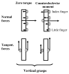
Normal and tangential digit forces during torque production, a schematic. Upper panel - normal forces; bottom panel - tangential forces. In the upper panel, the forces are drawn as vectors with their origin at the digit sensors. In the bottom panel, the tangential digit forces are represented by one vector (the VF force). The moment of the thumb and VF tangential forces is proportional to the difference in the magnitude of the forces. Note that the thumb force can be either in upward or downward direction. During the moment generation in the counterclockwise direction (pronation), the normal forces of index and middle fingers produce moments in pronation, i.e. in the required direction. Such fingers are called torque agonists. The ring and little fingers work in this task as torque antagonists: they generate moments in the opposite direction, clockwise.
Figure 7
Figure 7
Relations between the external torque generated by the suspended load (abscissa) and the moment produced by the normal forces of the fingers, Mn (ordinate). Group average data are shown (n=10). The data are for four different loads. The coefficients of the regression equations Mn =a+b(Torque) are: for load 0.5 kg, slope b=0.451, intercept a = 0.06; load 1.0 kg, b=0.473, a = 0.02; load 1.5 kg, b=0.492, a = −0.01; load 2.0 kg, b=0.504, a = −0.01. Note that the intercepts are very small; hence the regression lines pass very close to the origin of the system of coordinates. Consequently, the percentage contribution of Mn into the total moment exerted on the object by the performers remains constant. Since the sum Mn + Mt equals the total moment, the percentage contribution of Mn into the total moment is also invariant. (Adapted by permission from V.M. Zatsiorsky, R.W. Gregory, and M.L. Latash. Force and torque production in static multifinger prehension: biomechanics and control. I. Biomechanics. Biological Cybernetics, 2002, 87:50–57.)
Figure 8
Figure 8
Digit forces and moments for different external torques and loads. Group average data are shown (n = 10). (A) The position of the point of application of the VF normal force. The zero position corresponds to the application of the VF resultant force at the center of the thumb force sensor. (B) The VF normal force. (C). The thumb tangential (shear) force. Note that in panel C curves are almost parallel, which signifies the lack of interaction between the LOAD and TORQUE factors. (D) ‘Antagonist/agonist moment’ ratio. The ratio for the zero torque conditions was estimated from the equilibrium requirements under the assumption that the normal forces of the two pairs of agonist and antagonist fingers were equal. Antagonist moments were observed over the entire range of load-torque combinations. (Adapted by permission from V.M. Zatsiorsky, R.W.Gregory, and M.L.Latash. Force and torque production in static multifinger prehension: biomechanics and control. I. Biomechanics. Biological Cybernetics, 2002, 87:50–57.)
Figure 9
Figure 9. Experimental setup (left panel) and sources of the total moment by digits about the Z-axis (right panels)
Left panel: Thumb and finger sensors (shown as white cylinders) were attached to vertical aluminum bars, and a movable load (shown as a black cylinder) was attached to the long aluminum bar. MX, MY and MZ are the moments with respect to the global X-, Y- and Zaxes, respectively. By suspending the load at various locations along the horizontal bar, the different external torques about the Z-axis were exerted on the handle. The subjects were required to maintain the handle at rest. Right panel. Sources of the MZ. Line arrows are the forces and the dotted arrows are the moment arms, as described in the body of the text. (Adapted by permission from J.E. Shim, M.L. Latash, and V.M. Zatsiorsky. Prehension synergies in three dimensions. Journal of Neurophysiology, 2005a, 93: 766–776.)
Figure 10
Figure 10
Relations among forces under different external torques at the VF level. A: thumb and VF forces along the X-axis. B: thumb and VF forces along the Y-axis. C: thumb and VF forces along the Z-axis. (Adapted by permission from J.E. Shim, M.L. Latash, and V.M. Zatsiorsky. Prehension synergies in three dimensions. Journal of Neurophysiology, 2005a, 93: 766–776.)
Figure 11
Figure 11
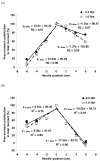
Free moment contribution to the total moment, %, as a function of the position of the neutral line of the hand from the moment axis (handle position). The handle was oriented vertically and its position with respect to the axis of rotation changed in different trials either in upward (positive) or downward (negative) directions. (a) Positive moment production (pronation efforts); (b) negative moment production (supination efforts). Averaged across subjects data are presented with standard error bars. To find the PZFMs, the regression lines should be extrapolated to the level of the zero contribution of the free moment. (Adapted by permission from J.K. Shim, M.L. Latash, and V.M. Zatsiorsky (2004) Finger coordination during moment production on a mechanically fixed object. Experimental Brain Research, 2004, 157: 457–467.)
Figure 12
Figure 12
Tangential forces of the thumb (left panel) and VF (right panel) as a function of the load and friction, high (H) or low (L), in three-digit grasps. The eight friction conditions were HHH, HLL, HHL, HLH, LLL, LHH, LHL, and LLH, where the letters correspond to the friction condition for the thumb, index and middle fingers, respectively. The difference between the high and low friction was approximately threefold. The friction sets with the thumb at the low friction contact (LLL, LHH, LHL and LLH) are printed with dotted lines. The solid lines represent the tasks with the high friction contact at the thumb. In the left panel, two smaller figure brackets show the synergic effects, i.e. the effect of friction at other digits on the thumb force. The numbers in the bottom right insets are the regression coefficients and intercepts (the regression model fit=ai+ki(1)L. was used for computations). Note the small values of the intercepts. Compare the right and the left panels: the thumb friction, H or L, induced opposite changes of the thumb and VF forces. Reprinted by permission from Niu X, Latash ML, and Zatsiorsky VM (2007) Prehension synergies in the grasps with complex friction patterns: local vs. synergic effects and the template control. Journal of Neurophysiology (in press).
Figure 13
Figure 13
Dependence of the middle finger normal force on the load for different friction sets. Group averages are shown. The numbers in the figure are the ki(3) coefficients and the coefficients of correlation squared (all r2≥0.98). The dotted lines designate the low friction contact at the middle finger. The two groups of the regression lines were mainly distinguished by the friction at the thumb (the synergic effect). The two small figure brackets show the local friction effect, i.e. the force variations induced by the high or low friction contact at the middle finger. At a given thumb friction, the forces were larger at the low friction contact at the middle finger. Adapted by permission from Niu X, Latash ML, and Zatsiorsky VM (2007) Prehension synergies in the grasps with complex friction patterns: local vs. synergic effects and the template control. Journal of Neurophysiology (in press).
Figure 14
Figure 14
The minimum normal forces to prevent slipping and support load for a pinch grasp performed with the T and I digits. By assumption, the normal forces exert no net moment. Results of mathematical modeling. θ is an inclination angle. Adapted by permission from Pataky TC, Latash ML, and Zatsiorsky VM (2004b) Prehension synergies during nonvertical grasping, II: Modeling and optimization. Biol Cybern. 91: 231–242.
Figure 15
Figure 15
Normal internal force (ordinate) as a function of the sine of the handle orientation angle (abscissa). The force is normalized by object weight (corresponding to the masses of 830, 1080 or 1330 g) and hence is dimensionless. Group average data are shown. Note that the curves to the right (supination) and to the left (pronation) on the zero inclination line are slightly concave and do not converge to the zero force levels. (Adapted by permission from T.C. Pataky, M.L. Latash, and V.M. Zatsiorsky. Prehension synergies during nonvertical grasping, I: experimental observations. Biological Cybernetics, 2004, 91: 148–158.)
Figure 16
Figure 16
Expanding the grasp force into the three fractions, a schematic. In the experiment, the subjects oscillated the object in the vertical direction. In the figure, an instant value of the grasp force is represented as the sum of the static, stato-dynamic and dynamic fractions. W is the object weight. The static relation is represented by a straight line. To obtain the static relation the subjects held at rest objects of different weight. The dynamic relation is represented by an ellipse. The relation is a grasp force-load force plot recorded in a single trial. (Reprinted by permission from V.M. Zatsiorsky, F. Gao, and M.L. Latash. Motor control goes beyond physics: differential effects of gravity and inertia on finger forces during manipulation of hand-held objects. Experimental Brain Research. 2005, 162: 300–308).
Figure 17
Figure 17
Static, dynamic and stato-dynamic relations between the grasp and load forces. The inertial forces are due to an oscillation of the vertically oriented handle at 1.5 Hz over about 10 cm in the vertical plane. The weights are 3.8, 6.3, 8.8, 11.3, and 13.8 N. Data from a representative subject are shown. W is the object weight and the load force is L=W+ma. The broken line represents the static load-grasp force relation; the solid line represents the stato-dynamic relation, and the ellipses illustrate the dynamic relations between the variable load force and the grasping force. Reprinted by permission from V.M. Zatsiorsky, F. Gao, and M.L. Latash. Motor control goes beyond physics: differential effects of gravity and inertia on finger forces during manipulation of hand-held objects. Experimental Brain Research. 2005, 162: 300–308.
Figure 18
Figure 18
Normal forces of the thumb and VF (A) and internal force and average normal force (B) versus the handle acceleration in the horizontal direction. Data shown are from a representative trial. The load was 11.3 N, the frequency was 3 Hz. Adapted from F. Gao, M.L. Latash, and V.M. Zatsiorsky. Internal forces during object manipulation. Experimental Brain Research. 2005, 165: 69–83.
Figure 19
Figure 19
Internal and resultant moments during horizontal oscillation of a horizontally oriented handle (frequency 1 Hz, weight 6.3 N). Data from a representative trial are shown. Dotted black line – moment of tangential forces; solid black line – moment of the normal forces; gray line –the total moment. During the manipulation, both Mn and Mt change in synchrony while the total moment remains relatively constant. Adapted by permission from F. Gao, M.L. Latash, and V.M. Zatsiorsky. Internal forces during object manipulation. Experimental Brain Research. 2005, 165: 69–83.
Figure 20
Figure 20
Tangential forces of the thumb versus tangential forces of the virtual finger across 25 trials. Data from a representative subject are shown. The subjects performed 25 trials at each of the external torques −1.0 Nm, −0.5 Nm, 0 Nm, 0.5 Nm and 1.0 Nm while the total load was always 14.9 N. In individual trials the forces were different. However, they were along the same line such that their sum was always constant. All the coefficients of correlation were −1.00. Because the moment of the tangential forces is proportional to the difference between the tangential forces, different location of the forces along the line is indicative of the different moment of tangential forces. The trial-to-trial variations of the moment of tangential forces were compensated by the matching changes of the moments of normal forces (not shown in the figure). Adapted by permission from J.K. Shim, M.L. Latash, and V.M. Zatsiorsky (2003). Prehension synergies: tria-to-trial variability and hierarchical organization of stable performance. Experimental Brain Research. 2003, 152: 173–184.
Figure 21
Figure 21
The normal forces of the index and little fingers at the different widths of the handle during the supination efforts of −1.0, −0.66 and −0.33 Nm. When the width increases, the force of the little finger decreases and the force of the index finger increases. As a result the moment of the normal forces decreases. The forces of the ‘central’ fingers (middle and the ring) that have the smaller moment arms do not change systematically. To avoid a messy picture these forces are not shown in the figure. (Reprinted by permission from V.M. Zatsiorsky, R.W. Gregory, and M.L. Latash. Force and torque production in static multifinger prehension: biomechanics and control. I. Biomechanics. Biological Cybernetics, 2002, 87:50–57.)
Figure 22
Figure 22
The relations between the normal forces of the thumb and the fingers. (a) the virtual finger force, (b) the little finger force, (c) the index finger force. Open symbols represent supination efforts and the closed symbols represent pronation efforts. Note the difference between the (a) panel and other two panels. The thumb transducer position was varied across trials: (a) middle position - the center line of the thumb sensor was at the midpoint of the handle; (b) bottom position - the center line of the thumb sensor was at the midpoint between the center lines of the ring and little finger sensors; and (c) upper position - situated at the midpoint between the center lines of the index and middle finger sensors. Group average data are shown. Adapted by permission from V.M. Zatsiorsky, F. Gao, and M.L. Latash. Prehension synergies: Effects of object geometry and prescribed torques. Experimental Brain Research, 2003, 148: 77–87.
Figure 23
Figure 23
Interrelations among the experimental variables over 25 trials. The data are from a representative subject. F and M designate the force and moment; superscripts n and t refer to the normal and tangential force components; subscripts th and vf refer to the thumb and virtual finger, respectively. A-1: Fthn correlated closely with Fvfn. This correlation was expected: in static tasks Fthn and Fvfn cancel each other. These two forces represent the first subset of variables mentioned in the text. A-2: Fvfn versus Mvfn. The correlation coefficients are close to zero. B-1: Ftht versus Fvft. The values of Ftht and Fvft are on a straight line. This correlation was expected because Ftht+Fvft=Constant(weightofhandle). The different location of Ftht and Fvft values along the straight line signifies the different magnitude of Mt. B-2: Fvft versus Mt[Mt=0.5(FvftFthv)d, where d = 68 mm]. As the sum Ftht and Fvft is constant a change in one of these forces determines the difference between their values and, hence, the moment that these force produce. B-3: Mt versus Mvfn. B-4: Mvfn versus Ftht. The variables in the panels B ( Ftht,Fvft,Mt,Mvfn) plus moment arm of the VF normal force constitute the second subset of variables mentioned in the text. The curved arrows signify the sequence of events resulting in the high correlation between Ftht and Mvfn (‘chain effects’). Such a correlation does not exist between Fvfn and Mvfn, see panel A-2. (Reprinted by permission from V.M. Zatsiorsky, M.L. Latash, F. Gao, and J.K. Shim. The principle of superposition in human prehension. Robotica, 2004, 22: 231–234.)
Figure 24
Figure 24
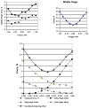
Decomposition of the normal forces of the middle finger during holding a 2.0 kg load at different external torques (Zatsiorsky et al. 2002). The data are from a representative subject. Upper left panel. Actual and ‘direct’ finger forces. The direct forces (dashed line) were computed as the products of the diagonal elements of the inter-finger connection matrix times the corresponding finger commands. Upper right panel. Enslaved forces, i.e. the difference between the actual and ‘direct’ forces. Bottom panel. Decomposition of the enslaving effects. Effects of the commands to other fingers on the middle finger force are presented. (Adapted by permission from V.M. Zatsiorsky, R.W. Gregory, and M.L. Latash. (2002b) Force and torque production in static multifinger prehension. II. Control. Biological Cybernetics, 87: 40–49.)
Figure 25
Figure 25
Comparison of the actual force data with the force patterns predicted by different optimization criteria. The norms of the following vectors were employed as cost functions: G1: Finger forces. G2: Finger forces normalized with respect to the maximal forces measured in single-finger tasks. G3: Finger forces normalized with respect to the maximal forces measured in a four-finger (IMRL) task. For the neural commands, the following objective function was optimized G4=(i=1i=4(ci)p)1/pmin(p=1,215) The norm powers from 1 to 15 were explored. The presented data are for p=3. Criteria G1, G2 and G3 did not predict well antagonist moments. (Adapted by permission from V.M. Zatsiorsky, R.W. Gregory, and M.L. Latash. (2002b) Force and torque production in static multifinger prehension. II. Control. Biological Cybernetics, 87: 40–49.)
Figure 26
Figure 26
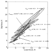
The dependence of the finger forces on object acceleration at different torques. Data from a representative subject are shown. Vertical oscillation of the handle, frequency 2 Hz. Left panel: the grasp force at different torques. Right panel: the index and little finger normal forces. The torques are described by the location of the object’s center of mass with respect to the grasp, Mi – middle (zero torque), R - right, L - left, 1 designates 1/6 Nm, 2 corresponds to 1/3 Nm. As an example, the symbol R2 represents the load location to the right of the center that results in the moment of −1/3 Nm. Such a moment—as seen from the subject—is in the clockwise direction (negative). To counterbalance this external moment/torque the subject should exert a counterclockwise (pronation, positive) moment of equal magnitude. Note: (1) in the left panel—the grasp force increases both with the acceleration and the torque; (2) in the right panel – when the fingers work as torque agonists the finger force increases with the acceleration; when the fingers work as torque antagonists the forces stay put. (Adapted from F. Gao, M.L. Latash, and V.M. Zatsiorsky. Maintaining rotational equilibrium during object manipulation: linear behavior of a highly non-linear system. Experimental Brain Research, 2006, 169(4):519–531).

Similar articles

Cited by

References

    1. Aoki T, Niu X, Latash ML, Zatsiorsky VM. Effects of friction at the digit-object interface on the digit forces in multi-finger prehension. Experimental Brain Research. 2006;172(4):425–438. - PMC - PubMed
    1. Aoki T, Latash ML, Zatsiorsky VM. Adjustments to different local friction in multi-finger prehension. Experimental Brain Research. 2007 [accepted for publication]; - PMC - PubMed
    1. Arbib MA, Iberall T, Lyons D. Coordinated control programs for movements of the hand. In: Goodwin AW, Darian-Smith I, editors. Hand Function and the Neocortex. Berlin: Springer Verlag; 1985. pp. 111–129.
    1. Arimoto S, Tahara K, Yamaguchi M, Nguyen PTA, Han HY. Principles of superposition for controlling pinch motions by means of robot fingers with soft tips. Robotica. 2001;19:21–28.
    1. Augurelle AS, Penta M, White O, Thonnard JL. The effects of a change in gravity on the dynamics of prehension. Experimental Brain Research. 2003a;148(4):533–40. - PubMed

Publication types

LinkOut - more resources