Review
. 2008 Nov;8(11):1864-78.
doi: 10.1039/b806446f. Epub 2008 Sep 19.

Microfabricated implants for applications in therapeutic delivery, tissue engineering, and biosensing

Affiliations
Review

Microfabricated implants for applications in therapeutic delivery, tissue engineering, and biosensing

Kristy M Ainslie et al. Lab Chip. 2008 Nov.

Abstract

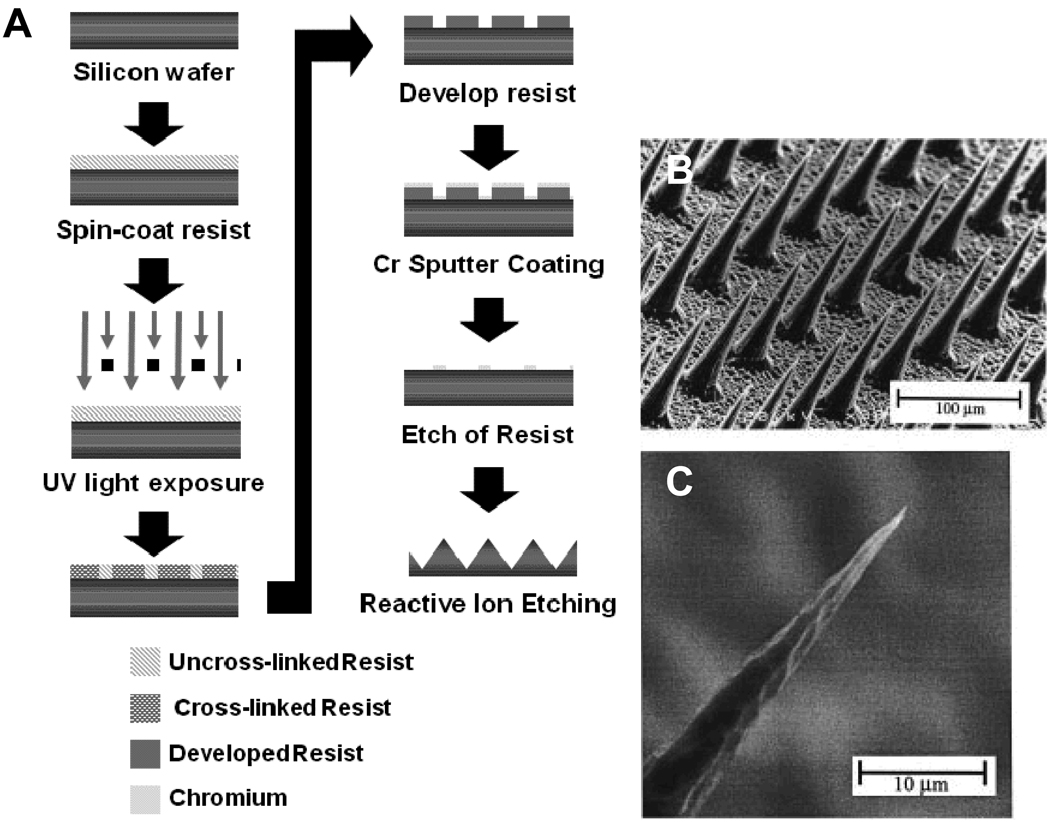
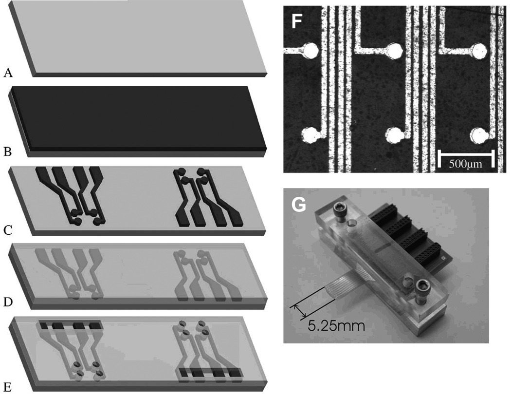
By adapting microfabrication techniques originally developed in the microelectronics industry novel devices for drug delivery, tissue engineering and biosensing have been engineered for in vivo use. Implant microfabrication uses a broad range of techniques including photolithography, and micromachining to create devices with features ranging from 0.1 to hundreds of microns with high aspect ratios and precise features. Microfabrication offers device feature scale that is relevant to the tissues and cells to which they are applied, as well as offering ease of en masse fabrication, small device size, and facile incorporation of integrated circuit technology. Utilizing these methods, drug delivery applications have been developed for in vivo use through many delivery routes including intravenous, oral, and transdermal. Additionally, novel microfabricated tissue engineering approaches propose therapies for the cardiovascular, orthopedic, and ocular systems, among others. Biosensing devices have been designed to detect a variety of analytes and conditions in vivo through both enzymatic-electrochemical reactions and sensor displacement through mechanical loading. Overall, the impact of microfabricated devices has had an impact over a broad range of therapies and tissues. This review addresses many of these devices and highlights their fabrication as well as discusses materials relevant to microfabrication techniques.


Figures

Figure 1
Figure 1
Bi-polymeric particles. (A) Process flow diagram for bi-polymeric particles. (B) Optical micrograph of hydrogel loaded particles. (C) Fluorescent micrograph of FITC-bovine serum albumin loaded hydrogel particles. (D) Fluorescent micrograph of multilayered hydrogel prepared with DNP-BSA, FITC-BSA and Texas-red-BSA (from outmost layer to inmost). The grey dotted-line box highlights the reservoir area and the red dotted-line box the outer area of the microdevice. (E) A fluorescent micrograph of combined filters of hydrogel-filled microdevices. (F) Schematic depicting the release of drug from spherical and microdevice particles.
Figure 2
Figure 2
Microfabrication of immunoisolation silicon nano-channeled membrane. (A) Process flow diagram adapted from Desai et al. The diffusion channel is 20–100 nm in thickness. (B) Optical micrograph of nano-channeled membrane with pores 78 nm in diameter. (C) Scanning electron micrograph of silicon nano-channeled membrane. Scale Bar = 1 µm
Figure 3
Figure 3
Microfabrication of micro- and nano-scale particles through PRINT method. (A) Process flow diagram for fabrication of PFPE mold. Adapted from Rolland et al. (B) Schematic of particle formation with PFPE stamp through modified micromolding. (C)-(E) Scanning electron micrographs of microfabricated PEG particles of various sizes and shapes.
Figure 4
Figure 4
Micromachining of microneedles made of silicon. (A) process flow diagram for microfabrication of silicon microneedles. Adapted from Henry et al. (B) and (C) scanning electron micrographs of microneedles.
Figure 5
Figure 5
Micromolding fabrication of PCL tissue engineering scaffolds. (A) Process flow diagram for development of micro-fabricated PCL films. Adapted from Sarkar et al., (B) Scanning electron micrograph of non-porous PCL scaffold. (C) Scanning electron micrograph of cross section of PCL scaffold.
Figure 6
Figure 6
Microfabrication of multi-electrode array for electroencephalography measurements. (A) A 50 micron thick Kapton film. (B) Sputter coating of 5 nanometers of titanium-tugsten alloy followed by 300 nm of gold. (C) Patterning of alloy through photolithography, resulting in a gold circuit consisting of an 8×8 grid of 64 electrodes and connection pads. (D) Spin coating of SU-8 over entire surface. (E) Photolithographic patterning of SU-8 to expose each electrode and connection pads. (F) Scanning electron micrograph of electrode surface. The light areas are the gold substrate and the black areas the Kapton film. (G) Electrodes with circuit board. Adapted from Hollenberg et al.

References

    1. Madou M. Fundamentals of Microfabrication: The Science of Miniaturization. ed. 2nd. New York, NY: CRC Press; 2002. p. 723.
    1. Lim JY, Donahue HJ. Tissue Engineering. 2007;13:1879. - PubMed
    1. Khademhosseini A, Langer R, Borenstein J, Vacanti JP. Proceedings of the National Academy of Sciences of the United States of America. 2006;103:2480. - PMC - PubMed
    1. Jung DR, Kapur R, Adams T, Giuliano KA, Mrksich M, Craighead HG, Taylor DL. Critical Reviews in Biotechnology. 2001;21:111. - PubMed
    1. Champion JA, Katare YK, Mitragotri S. J Control Release. 2007;121:3. - PMC - PubMed

MeSH terms