Safety of localizing epilepsy monitoring intracranial electroencephalograph electrodes using MRI: radiofrequency-induced heating
- PMID: 18972332
- PMCID: PMC2883075
- DOI: 10.1002/jmri.21583
Safety of localizing epilepsy monitoring intracranial electroencephalograph electrodes using MRI: radiofrequency-induced heating
Abstract
Purpose: To investigate heating during postimplantation localization of intracranial electroencephalograph (EEG) electrodes by MRI.
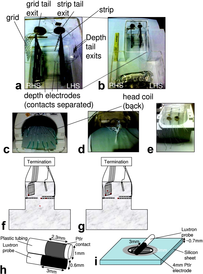
Materials and methods: A phantom patient with a realistic arrangement of electrodes was used to simulate tissue heating during MRI. Measurements were performed using 1.5 Tesla (T) and 3T MRI scanners, using head- and body-transmit RF-coils. Two electrode-lead configurations were assessed: a "standard" condition with external electrode-leads physically separated and a "fault" condition with all lead terminations electrically shorted.
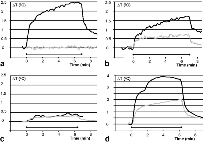
Results: Using a head-transmit-receive coil and a 2.4 W/kg head-average specific absorption rate (SAR) sequence, at 1.5T the maximum temperature change remained within safe limits (<1 degrees C). Under "standard" conditions, we observed greater heating (<or=2.0 degrees C) at 3T on one system and similar heating (<1 degrees C) on a second, compared with the 1.5T system. In all cases these temperature maxima occurred at the grid electrode. In the "fault" condition, larger temperature increases were observed at both field strengths, particularly for the depth electrodes. Conversely, with a body-transmit coil at 3T significant heating (+6.4 degrees C) was observed (same sequence, 1.2/0.5 W/kg head/body-average) at the grid electrode under "standard" conditions, substantially exceeding safe limits. These temperature increases neglect perfusion, a major source of heat dissipation in vivo.
Conclusion: MRI for intracranial electrode localization can be performed safely at both 1.5T and 3T provided a head-transmit coil is used, electrode leads are separated, and scanner-reported SARs are limited as determined in advance for specific scanner models, RF coils and implant arrangements. Neglecting these restrictions may result in tissue injury.
Copyright (c) 2008 Wiley-Liss, Inc.
Figures

References
-
- Lemieux L, Allen PJ, Franconi F, Symms MR, Fish DR. Recording of EEG during fMRI experiments: patient safety. Magn Reson Med. 1997;38:943–952. - PubMed
-
- Georgi JC, Stippich C, Tronnier VM, Heiland S. Active deep brain stimulation during MRI: a feasibility study. Magn Reson Med. 2004;51:380–388. - PubMed
-
- Carmichael DW, Pinto S, Limousin-Dowsey P, et al. Functional MRI with active, fully implanted, deep brain stimulation systems: safety and experimental confounds. Neuroimage. 2007;37:508–517. - PubMed
-
- Kanal E, Meltzer CC, Adelson PD, Scheuer MP. Platinum subdural grid: MR imaging compatibility testing. Radiology. 1999;211:886–888. - PubMed
Publication types
MeSH terms
Grants and funding
LinkOut - more resources
Full Text Sources
Medical
Miscellaneous