Clinical Trial
. 2009 Jan;467(1):119-27.
doi: 10.1007/s11999-008-0598-4. Epub 2008 Nov 1.

Combined anteversion technique for total hip arthroplasty

Affiliations
Clinical Trial

Combined anteversion technique for total hip arthroplasty

Lawrence D Dorr et al. Clin Orthop Relat Res. 2009 Jan.

Abstract

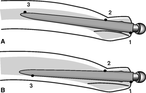
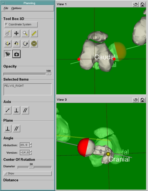
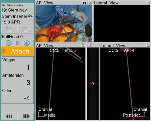
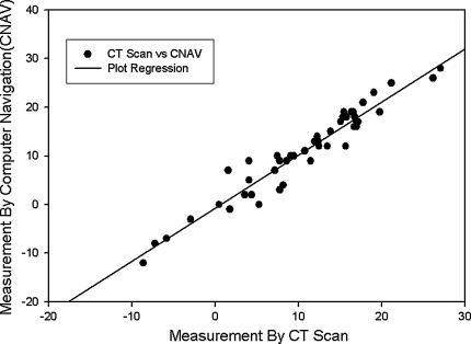
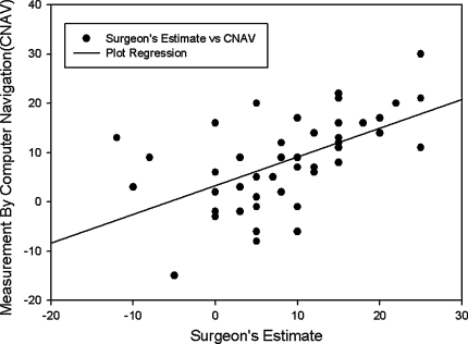
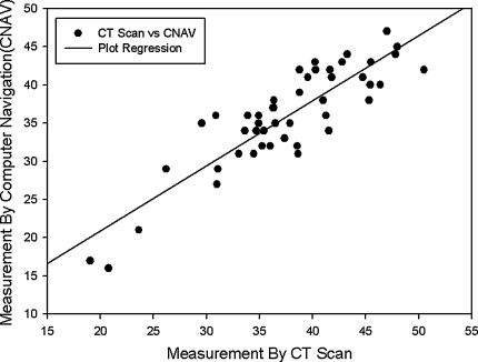
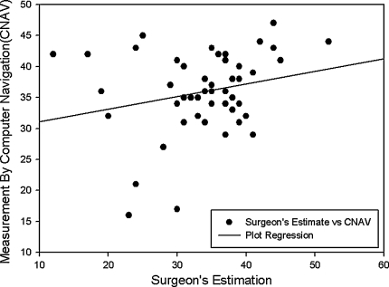
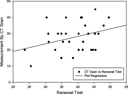
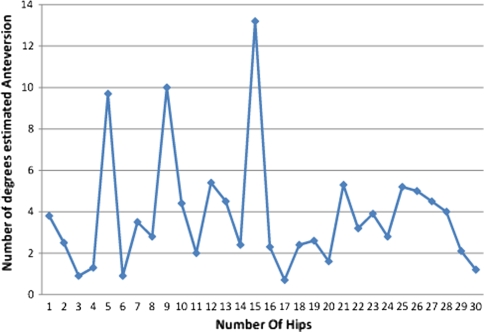
Combined cup and stem anteversion in THA based on femoral anteversion has been suggested as a method to compensate for abnormal femoral anteversion. We investigated the combined anteversion technique using computer navigation. In 47 THAs, the surgeon first estimated the femoral broach anteversion and validated the position by computer navigation. The broach was then measured with navigation. The navigation screen was blocked while the surgeon estimated the anteversion of the broach. This provided two estimates of stem anteversion. The navigated stem anteversion was validated by postoperative CT scans. All cups were implanted using navigation alone. We determined precision (the reproducibility) and bias (how close the average test number is to the true value) of the stem position. Comparing the surgeon estimate to navigation anteversion, the precision of the surgeon was 16.8 degrees and bias was 0.2 degrees ; comparing the navigation of the stem to postoperative CT anteversion, the precision was 4.8 degrees and bias was 0.2 degrees , meaning navigation is accurate. Combined anteversion by postoperative CT scan was 37.6 degrees +/- 7 degrees (standard deviation) (range, 19 degrees -50 degrees ). The combined anteversion with computer navigation was within the safe zone of 25 degrees to 50 degrees for 45 of 47 (96%) hips. Femoral stem anteversion had a wide variability.

Level of evidence: Level II, therapeutic study. See the Guidelines for Authors for a complete description of levels of evidence.


Figures

Fig. 1A–B
Fig. 1A–B
(A) Diagram illustrates the anteversion of the femoral stem controlled by the anteversion of the neck, the anteroposterior isthmus (anterior cortex and true femoral calcar) at the level of the lesser trochanter, and the posterior fin of bone in types A and B. Femoral stem anteversion decreases as the bow of the femur increases or the posterior fin thickness increases. 1, 2, and 3 are three points of rotational stability. (B) Type C osteoporotic bone has a wide intramedullary canal so the isthmus and diaphysis have less influence on the stem anteversion. 1, 2, and 3 are three points of rotational stability.
Fig. 2
Fig. 2
A screenshot image of the Navitrack® CT scan-based module shows how femoral anteversion is determined. The virtual model femoral head is positioned over the implant femoral head and aligned until the axis of the model coincides with the axis of the proximal head and neck. Anteversion is the angle between this axis and the femoral plane established as the plane passing through both medial and lateral epicondyles of the femur and the mid-high point of the greater trochanter.
Fig. 3
Fig. 3
A screenshot image of the Navitrack® navigation screen shows femoral anteversion when using a tracked femoral broach or stem inserter as shown in the inset in the upper left-hand corner. Anteversion is 3°, stem is in 1° valgus, and with a neutral head the offset of the femoral head is decreased 4 mm. CC is craniocaudal height of the femoral head center which in increased 5 mm; mL is the mediolateral displacement of the head center which is 5 mm medial; AP is anteroposterior displacement of head center which is 4 mm posterior which contributes to retroversion of the stem (see Fig. 1).
Fig. 4
Fig. 4
Femoral stem anteversion of 47 APR® stems measured by computer navigation compared to CT scan shows excellent regression. The solid line represents a simple linear regression fit (r = 0.97, p = 0.000).
Fig. 5
Fig. 5
Femoral stem anteversion of 47 APR® broaches measured by computer navigation compared to surgeon’s estimation shows wide scatter. The solid line represents a simple linear regression fit (r = 0.57, p = 0.000).
Fig. 6
Fig. 6
Combined cup and stem anteversion of 47 hips measured by computer navigation compared to CT scan shows good regression. The solid line represents a simple linear regression fit (r = 0.88, p = 0.000).
Fig. 7
Fig. 7
Combined cup and stem anteversion of 47 hips measured by computer navigation compared to surgeon’s estimation shows poor regression with wide scatter. The solid line represents a simple linear regression fit (r = 0.24, p = 0.11).
Fig. 8
Fig. 8
A plot of combined cup and stem anteversion of 33 hips measured by computer navigation compared to Ranawat test shows wide scatter. The solid line represents a simple linear regression fit (r = 0.33, p = 0.11).
Fig. 9
Fig. 9
The estimated anteversion (degrees) could be determined within 5° of the reference value by surgeon estimate alone after a learning curve of 15 hips.

Comment in

Similar articles

Cited by

References

    1. ASTM. Standard Practice for Use of the Terms Precision and Bias in ASTM Test Methods. In: Annual Book of ASTM Standards ed. Philadelphia, PA: American Society for Testing and Materials; 2002:E177–E190a.
    1. {'text': '', 'ref_index': 1, 'ids': [{'type': 'DOI', 'value': '10.1016/S0030-5898(05)70227-3', 'is_inner': False, 'url': 'https://doi.org/10.1016/s0030-5898(05)70227-3'}, {'type': 'PubMed', 'value': '11689370', 'is_inner': True, 'url': 'https://pubmed.ncbi.nlm.nih.gov/11689370/'}]}
    2. Barrack RL, Lavernia C, Ries M, Thornberry R, Tozakoglou E. Virtual reality computer animation of the effect of component position and design on stability after total hip arthroplasty. Orthop Clin North Am. 2001;32:569–577. - PubMed
    1. {'text': '', 'ref_index': 1, 'ids': [{'type': 'DOI', 'value': '10.1016/0169-2607(92)90043-7', 'is_inner': False, 'url': 'https://doi.org/10.1016/0169-2607(92)90043-7'}, {'type': 'PubMed', 'value': '1395533', 'is_inner': True, 'url': 'https://pubmed.ncbi.nlm.nih.gov/1395533/'}]}
    2. Best DE, Horii SC, Bennett W, Thomson B, Snavely D. Review of the American College of Radiology–National Electrical Manufacturers’ Association standards activity. Comput Methods Programs Biomed. 1992;37:305–309. - PubMed
    1. {'text': '', 'ref_index': 1, 'ids': [{'type': 'PubMed', 'value': '1561424', 'is_inner': True, 'url': 'https://pubmed.ncbi.nlm.nih.gov/1561424/'}]}
    2. Bidgood WD Jr, Horii SC. Introduction to the ACR-NEMA DICOM standard. Radiographics. 1992;12:345–355. - PubMed
    1. {'text': '', 'ref_index': 1, 'ids': [{'type': 'DOI', 'value': '10.1097/00003086-199810000-00003', 'is_inner': False, 'url': 'https://doi.org/10.1097/00003086-199810000-00003'}, {'type': 'PubMed', 'value': '9917587', 'is_inner': True, 'url': 'https://pubmed.ncbi.nlm.nih.gov/9917587/'}]}
    2. DiGioia AM, Jaramaz B, Blackwell M, Simon DA, Morgan F, Moody JE, Nikou C, Colgan BD, Aston CA, Labarca RS, Kischell E, Kanade T. The Otto Aufranc Award. Image guided navigation system to measure intraoperatively acetabular implant alignment. Clin Orthop Relat Res. 1998;355:8–22. - PubMed

MeSH terms