Slice-selective RF pulses for in vivo B1+ inhomogeneity mitigation at 7 tesla using parallel RF excitation with a 16-element coil
- PMID: 19025908
- PMCID: PMC2635025
- DOI: 10.1002/mrm.21739
Slice-selective RF pulses for in vivo B1+ inhomogeneity mitigation at 7 tesla using parallel RF excitation with a 16-element coil
Abstract
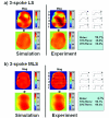
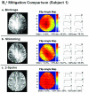
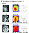
Slice-selective RF waveforms that mitigate severe B1+ inhomogeneity at 7 Tesla using parallel excitation were designed and validated in a water phantom and human studies on six subjects using a 16-element degenerate stripline array coil driven with a butler matrix to utilize the eight most favorable birdcage modes. The parallel RF waveform design applied magnitude least-squares (MLS) criteria with an optimized k-space excitation trajectory to significantly improve profile uniformity compared to conventional least-squares (LS) designs. Parallel excitation RF pulses designed to excite a uniform in-plane flip angle (FA) with slice selection in the z-direction were demonstrated and compared with conventional sinc-pulse excitation and RF shimming. In all cases, the parallel RF excitation significantly mitigated the effects of inhomogeneous B1+ on the excitation FA. The optimized parallel RF pulses for human B1+ mitigation were only 67% longer than a conventional sinc-based excitation, but significantly outperformed RF shimming. For example the standard deviations (SDs) of the in-plane FA (averaged over six human studies) were 16.7% for conventional sinc excitation, 13.3% for RF shimming, and 7.6% for parallel excitation. This work demonstrates that excitations with parallel RF systems can provide slice selection with spatially uniform FAs at high field strengths with only a small pulse-duration penalty.
(c) 2008 Wiley-Liss, Inc.
Figures


Similar articles
-
Array-compressed parallel transmit pulse design.Magn Reson Med. 2016 Oct;76(4):1158-69. doi: 10.1002/mrm.26020. Epub 2015 Oct 28. Magn Reson Med. 2016. PMID: 26510117 Free PMC article.
-
High-flip-angle slice-selective parallel RF transmission with 8 channels at 7 T.J Magn Reson. 2008 Nov;195(1):76-84. doi: 10.1016/j.jmr.2008.08.012. Epub 2008 Aug 30. J Magn Reson. 2008. PMID: 18799336 Free PMC article.
-
Parallel RF transmission with eight channels at 3 Tesla.Magn Reson Med. 2006 Nov;56(5):1163-71. doi: 10.1002/mrm.21042. Magn Reson Med. 2006. PMID: 17036289
-
Parallel RF transmission in MRI.NMR Biomed. 2006 May;19(3):393-400. doi: 10.1002/nbm.1049. NMR Biomed. 2006. PMID: 16705630 Review.
-
Generalized encoding through the use of selective excitation in accelerated parallel MRI.NMR Biomed. 2006 May;19(3):379-92. doi: 10.1002/nbm.1047. NMR Biomed. 2006. PMID: 16705639 Review.
Cited by
-
Cerebral TOF angiography at 7T: Impact of B1 (+) shimming with a 16-channel transceiver array.Magn Reson Med. 2014 Mar;71(3):966-77. doi: 10.1002/mrm.24749. Magn Reson Med. 2014. PMID: 23640915 Free PMC article.
-
Local SAR compression with overestimation control to reduce maximum relative SAR overestimation and improve multi-channel RF array performance.MAGMA. 2021 Feb;34(1):153-163. doi: 10.1007/s10334-020-00890-0. Epub 2020 Sep 22. MAGMA. 2021. PMID: 32964299 Free PMC article.
-
Large dynamic range relative B1+ mapping.Magn Reson Med. 2016 Aug;76(2):490-9. doi: 10.1002/mrm.25884. Epub 2015 Aug 26. Magn Reson Med. 2016. PMID: 26308375 Free PMC article.
-
High-resolution gradient-recalled echo imaging at 9.4T using 16-channel parallel transmit simultaneous multislice spokes excitations with slice-by-slice flip angle homogenization.Magn Reson Med. 2017 Sep;78(3):1050-1058. doi: 10.1002/mrm.26501. Epub 2016 Oct 23. Magn Reson Med. 2017. PMID: 27774641 Free PMC article.
-
Evolution of UHF Body Imaging in the Human Torso at 7T: Technology, Applications, and Future Directions.Top Magn Reson Imaging. 2019 Jun;28(3):101-124. doi: 10.1097/RMR.0000000000000202. Top Magn Reson Imaging. 2019. PMID: 31188271 Free PMC article. Review.
References
-
- Silver MS, Joseph RI, Hoult DI. Highly selective 90° and 180° pulse generation. J Magn Reson. 1984;59:347–351.
-
- Garwood M, DelaBarre L. The return of the frequency sweep: designing adiabatic pulses for contemporary NMR. J Magn Reson. 2001;153(2):155–177. - PubMed
-
- Ibrahim TS, Lee R, Baertlein BA, Abduljalil AM, Zhu H, Robitaille PM. Effect of RF coil excitation on field inhomogeneity at ultra high fields: a field optimized TEM resonator. Magn Reson Imaging. 2001;19(10):1339–1347. - PubMed
-
- Adriany G, Van de Moortele PF, Wiesinger F, Moeller S, Strupp JP, Andersen P, Snyder C, Zhang X, Chen W, Pruessmann KP, Boesiger P, Vaughan T, Ugurbil K. Transmit and receive transmission line arrays for 7 Tesla parallel imaging. Magn Reson Med. 2005;53(2):434–445. - PubMed
Publication types
MeSH terms
Grants and funding
LinkOut - more resources
Full Text Sources
Other Literature Sources
Medical
Research Materials
Miscellaneous

