

Mechanical model of neural tissue displacement during Lorentz effect imaging
- PMID: 19097218
- PMCID: PMC2710514
- DOI: 10.1002/mrm.21772
Mechanical model of neural tissue displacement during Lorentz effect imaging
Abstract
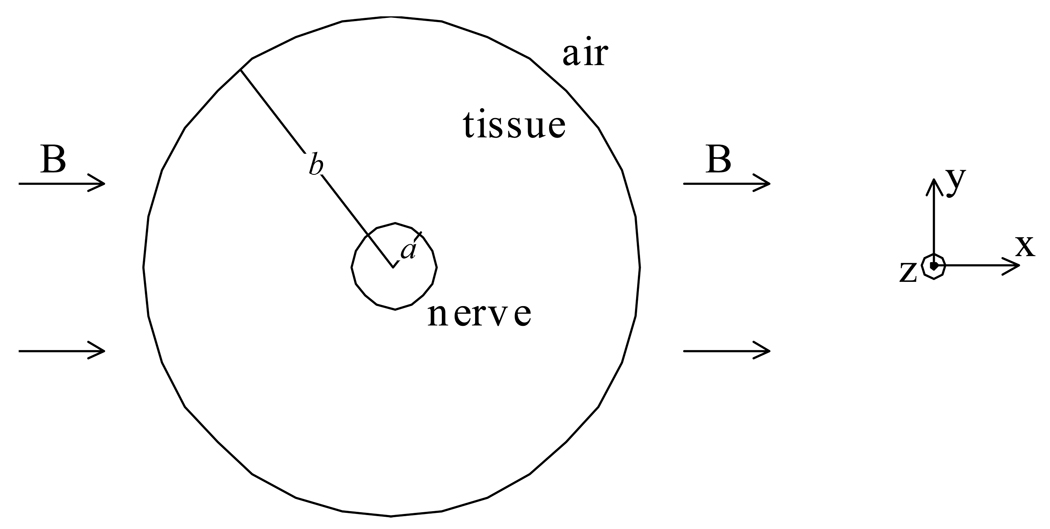
Allen Song and coworkers recently proposed a method for MRI detection of biocurrents in nerves called "Lorentz effect imaging." When exposed to a magnetic field, neural currents are subjected to a Lorentz force that moves the nerve. If the displacement is large enough, an artifact is predicted in the MR signal. In this work, the displacement of a nerve of radius a in a surrounding tissue of radius b and shear modulus mu is analyzed. The nerve carries a current density J and lies in a magnetic field B. The solution to the resulting elasticity problem indicates that the nerve moves a distance BJ/4mu a2ln(b/a). Using realistic parameters for a human median nerve in a 4T field, this calculated displacement is 0.013 microm or less. The distribution of displacement is widespread throughout the tissue, and is not localized near the nerve. This displacement is orders of magnitude too small to be detected by conventional MRI methods.
Figures

Similar articles
-
Elasticity reconstruction from displacement and confidence measures of a multi-compressed ultrasound RF sequence.IEEE Trans Ultrason Ferroelectr Freq Control. 2008 Feb;55(2):319-26. doi: 10.1109/TUFFC.2008.651. IEEE Trans Ultrason Ferroelectr Freq Control. 2008. PMID: 18334339
-
Preliminary investigation of multiparametric strain Z-score (MPZS) computation using displacement encoding with simulated echoes (DENSE) and radial point interpretation method (RPIM).J Magn Reson Imaging. 2016 Oct;44(4):993-1002. doi: 10.1002/jmri.25239. Epub 2016 Mar 31. J Magn Reson Imaging. 2016. PMID: 27038246 Free PMC article.
-
The movement of a nerve in a magnetic field: application to MRI Lorentz effect imaging.Med Biol Eng Comput. 2014 May;52(5):491-8. doi: 10.1007/s11517-014-1153-y. Epub 2014 Apr 12. Med Biol Eng Comput. 2014. PMID: 24728667 Free PMC article.
-
Sonoelastography: musculoskeletal applications.Radiology. 2014 Sep;272(3):622-33. doi: 10.1148/radiol.14121765. Radiology. 2014. PMID: 25153273 Review.
-
Ventricular mechanics: techniques and applications.Magn Reson Imaging Clin N Am. 2015 Feb;23(1):7-13. doi: 10.1016/j.mric.2014.08.005. Magn Reson Imaging Clin N Am. 2015. PMID: 25476669 Review.
Cited by
-
Mechanical bidomain model of cardiac tissue.Phys Rev E Stat Nonlin Soft Matter Phys. 2010 Oct;82(4 Pt 1):041904. doi: 10.1103/PhysRevE.82.041904. Epub 2010 Oct 5. Phys Rev E Stat Nonlin Soft Matter Phys. 2010. PMID: 21230310 Free PMC article.
-
Fast human brain magnetic resonance responses associated with epileptiform spikes.Magn Reson Med. 2010 Dec;64(6):1728-38. doi: 10.1002/mrm.22561. Epub 2010 Aug 30. Magn Reson Med. 2010. PMID: 20806355 Free PMC article.
-
Magnetic fields from skeletal muscles: a valuable physiological measurement?Front Physiol. 2015 Aug 10;6:228. doi: 10.3389/fphys.2015.00228. eCollection 2015. Front Physiol. 2015. PMID: 26321960 Free PMC article. No abstract available.
-
Direct neural current imaging in an intact cerebellum with magnetic resonance imaging.Neuroimage. 2016 May 15;132:477-490. doi: 10.1016/j.neuroimage.2016.01.059. Epub 2016 Feb 17. Neuroimage. 2016. PMID: 26899788 Free PMC article.
-
Responses to membrane potential-modulating ionic solutions measured by magnetic resonance imaging of cultured cells and in vivo rat cortex.Elife. 2025 Jul 3;13:RP101642. doi: 10.7554/eLife.101642. Elife. 2025. PMID: 40608052 Free PMC article.
References
-
- Joy M, Scott G, Henkelman M. In vivo detection of applied electric currents by magnetic resonance imaging. Magn Reson Imaging. 1989;7:89–94. - PubMed
-
- Bodurka J, Jesmanowicz A, Hyde JS, Xu H, Estkowski L, Li S-J. Current-induced magnetic resonance phase imaging. J Magn Reson. 1999;137:265–271. - PubMed
-
- Scott GC, Joy MLG, Armstrong RL, Henkelman RM. Measurement of non-uniform current density by magnetic resonance. IEEE Trans Med Imaging. 1991;10:362–374. - PubMed
-
- Scott GC, Joy MLG, Armstrong RL, Henkelman RM. Sensitivity of magnetic resonance current density imaging. J Magn Reson. 1992;97:235–254. - PubMed
-
- Joy MLG, Lebedev VP, Gatti J. Imaging of current density and current pathways in rabbit brain during transcranial electrostimulation. IEEE Trans Biomed Eng. 1999;46:1139–1149. - PubMed
Publication types
MeSH terms
Grants and funding
LinkOut - more resources
Full Text Sources
Medical
Research Materials
