

An easily identifiable anatomic landmark for fluoroscopically guided sacroplasty: anatomic description and validation with treatment in 13 patients
- PMID: 19193750
- PMCID: PMC7051671
- DOI: 10.3174/ajnr.A1502
An easily identifiable anatomic landmark for fluoroscopically guided sacroplasty: anatomic description and validation with treatment in 13 patients
Abstract
Background and purpose: Percutaneous sacroplasty has recently gained attention as a potential treatment for sacral insufficiency fractures. We describe a readily identifiable fluoroscopic landmark that facilitates needle placement and validate this with virtual needle placement by using CT data and fluoroscopically guided treatment in 13 patients.
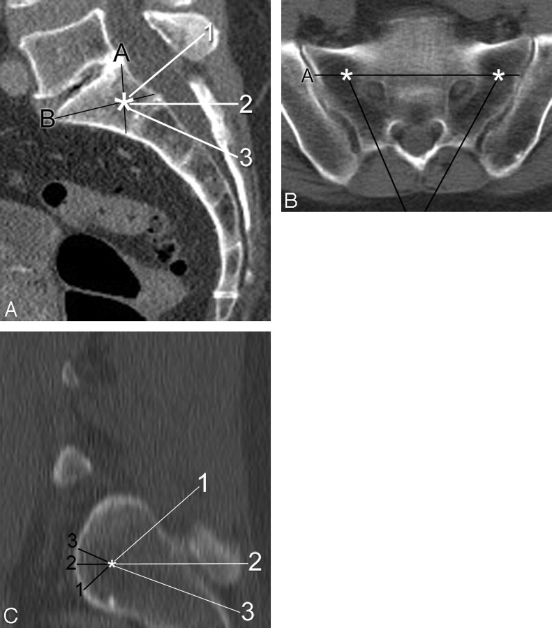
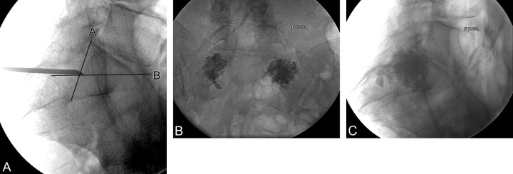
Materials and methods: From CTs of 100 consecutive patients, the optimal target zone for needle placement in the sacral ala was defined at the intersection of lines from each of the corners of the first sacral segment, which is readily identifiable on lateral fluoroscopy. We then measured the distance from that virtual target point to the anterior sacral cortex by using the CT data for 3 specific trajectories: 1) parallel to the L5-S1 disk, 2) axial with respect to the patient, and 3) along the long axis of the sacrum. Case records of 13 consecutive patients treated by using this technique were also reviewed.
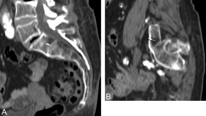
Results: The mean distances for the 3 trajectories were 11.3 mm, 11.2 mm, and 12.8 mm, respectively. Needle placement would have been outside the anterior sacral cortex in 3 patients. Review of preprocedure imaging easily identified this potential breach. During treatment, needle placement by using the landmark was successful in all patients, and there were no complications.
Conclusions: A safe target for sacroplasty needle placement in the superolateral sacral ala can be defined by using the intersection of lines drawn from the corners of the first sacral segment. We validated this landmark by using it for treatment in 13 patients. Further studies evaluating clinical outcomes following sacroplasty will be necessary.
Figures
Similar articles
-
Safety and effectiveness of percutaneous sacroplasty: a single-centre experience in 58 consecutive patients with tumours or osteoporotic insufficient fractures treated under fluoroscopic guidance.Eur Radiol. 2013 Oct;23(10):2764-72. doi: 10.1007/s00330-013-2881-3. Epub 2013 May 21. Eur Radiol. 2013. PMID: 23689309 Clinical Trial.
-
Combination of long- and short-axis alar sacroplasty techniques under fluoroscopic guidance for osteoporotic sacral insufficiency fracture.J Orthop Surg Res. 2021 Apr 17;16(1):269. doi: 10.1186/s13018-021-02409-2. J Orthop Surg Res. 2021. PMID: 33865421 Free PMC article.
-
Vertebroplasty of the first sacral vertebra.Pain Physician. 2009 May-Jun;12(3):651-7. Pain Physician. 2009. PMID: 19461832
-
Sacroplasty.Tech Vasc Interv Radiol. 2009 Mar;12(1):51-63. doi: 10.1053/j.tvir.2009.06.006. Tech Vasc Interv Radiol. 2009. PMID: 19769907 Review.
-
Sacral Fractures and Sacroplasty.Neuroimaging Clin N Am. 2019 Nov;29(4):515-527. doi: 10.1016/j.nic.2019.07.003. Epub 2019 Aug 27. Neuroimaging Clin N Am. 2019. PMID: 31677727 Review.
Cited by
-
Safety and effectiveness of percutaneous sacroplasty: a single-centre experience in 58 consecutive patients with tumours or osteoporotic insufficient fractures treated under fluoroscopic guidance.Eur Radiol. 2013 Oct;23(10):2764-72. doi: 10.1007/s00330-013-2881-3. Epub 2013 May 21. Eur Radiol. 2013. PMID: 23689309 Clinical Trial.
-
Sacroplasty for cancer-associated insufficiency fractures.Neurosurgery. 2015 Apr;76(4):446-50; discussion 450. doi: 10.1227/NEU.0000000000000658. Neurosurgery. 2015. PMID: 25635890 Free PMC article.
-
Sacral Insufficiency Fractures Mimicking Lumbar Spine Pathology.Asian Spine J. 2016 Jun;10(3):558-64. doi: 10.4184/asj.2016.10.3.558. Epub 2016 Jun 16. Asian Spine J. 2016. PMID: 27340538 Free PMC article.
-
Effects of Percutaneous Sacroplasty on Pain and Mobility in Sacral Insufficiency Fracture.J Korean Neurosurg Soc. 2017 Jan 1;60(1):60-66. doi: 10.3340/jkns.2016.0505.010. Epub 2016 Dec 29. J Korean Neurosurg Soc. 2017. PMID: 28061493 Free PMC article.
-
Combination of long- and short-axis alar sacroplasty techniques under fluoroscopic guidance for osteoporotic sacral insufficiency fracture.J Orthop Surg Res. 2021 Apr 17;16(1):269. doi: 10.1186/s13018-021-02409-2. J Orthop Surg Res. 2021. PMID: 33865421 Free PMC article.
References
Publication types
MeSH terms
LinkOut - more resources
Full Text Sources
Medical
Research Materials