. 2008;18(4):171-86.

Whole-motion model of perception during forward- and backward-facing centrifuge runs

Affiliations

Whole-motion model of perception during forward- and backward-facing centrifuge runs

Jan E Holly et al. J Vestib Res. 2008.

Abstract

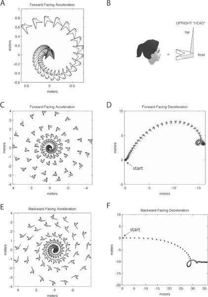
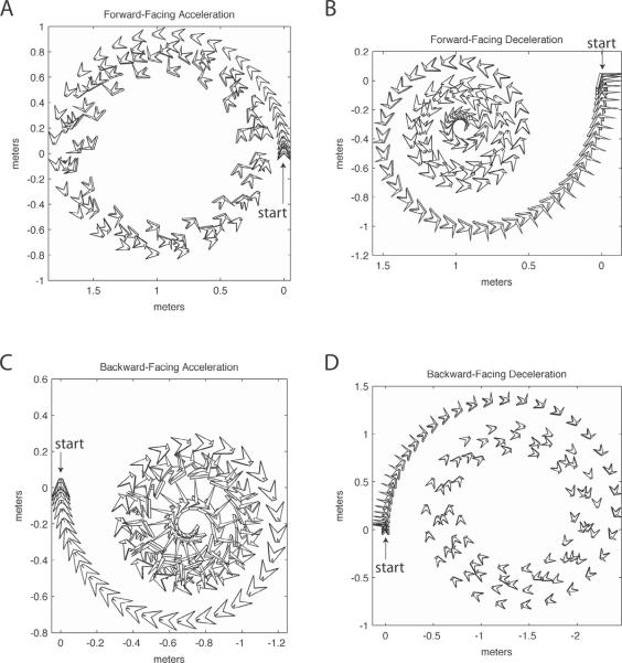
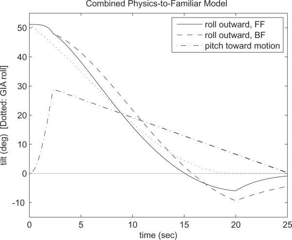
Illusory perceptions of motion and orientation arise during human centrifuge runs without vision. Asymmetries have been found between acceleration and deceleration, and between forward-facing and backward-facing runs. Perceived roll tilt has been studied extensively during upright fixed-carriage centrifuge runs, and other components have been studied to a lesser extent. Certain, but not all, perceptual asymmetries in acceleration-vs-deceleration and forward-vs-backward motion can be explained by existing analyses. The immediate acceleration-deceleration roll-tilt asymmetry can be explained by the three-dimensional physics of the external stimulus; in addition, longer-term data has been modeled in a standard way using physiological time constants. However, the standard modeling approach is shown in the present research to predict forward-vs-backward-facing symmetry in perceived roll tilt, contradicting experimental data, and to predict perceived sideways motion, rather than forward or backward motion, around a curve. The present work develops a different whole-motion-based model taking into account the three-dimensional form of perceived motion and orientation. This model predicts perceived forward or backward motion around a curve, and predicts additional asymmetries such as the forward-backward difference in roll tilt. This model is based upon many of the same principles as the standard model, but includes an additional concept of familiarity of motions as a whole.


Figures

Figure 1
Figure 1
The roll tilt of the gravito-inertial acceleration (GIA) vector during rotation of a subject in a fixed-carriage centrifuge. The GIA is the sum of the centripetal acceleration and an Earth-upward vector of magnitude g (equaling that of the gravitational acceleration), as explained in the text.
Figure 2
Figure 2
Laws-of-physics-only predicted perceived roll and pitch tilt during first 4 s of counterclockwise-rotating 1-m radius centrifuge acceleration and deceleration at 10°/s2; initial velocity before deceleration is 200°/s2, so a deceleration to stop would take 20 s. Both roll and pitch tilt exhibit an acceleration-deceleration asymmetry. Because the centrifuge deceleration begins with a perceived head orientation of roll tilt (to match the GIA), the clockwise angular acceleration from centrifuge deceleration causes the head's perceived orientation to rotate clockwise in yaw, into a pitch-down and less-roll orientation. Head orientations relative to vertical are shown next to the curves. Roll tilt of the GIA is shown by the dotted lines.
Figure 3
Figure 3
Model comparison. (A) Standard Model, consisting of the core of many models in the literature. Change in perceived angular velocity is given by angular acceleration and decays with time constant τa. Change in perceived linear velocity is given by perceived linear acceleration, as derived by subtracting the perceived gravity vector from the GIA, and decays with time constant τl. Change in perceived position is given by perceived linear velocity. For perceived orientation, vectors g, i, and j are earth-fixed vectors given in head coordinates, indicating upward and any perpendicular pair of headings such as “north” and “west”, respectively. Change in perceived orientation is given by perceived angular velocity but with an additional factor: θ gives direction angle, according to the right-hand rule, used in simulating the tendency for perceived vertical to move toward the GIA direction, with time constant τt. Arrows indicate which variables are used in which equations. (B) Whole-Motion Model motivated by the concept of familiarity during forward and backward motion. Perceived angular velocity is about the perceived earth-vertical axis, and heading is based upon angular velocity. Perceived roll angle θr of the subject's y-axis (interaural axis) from earth-horizontal, and pitch angle θp of the subject's x-axis (naso-occipital axis) from earth-horizontal, are those that match the GIA: θr matches the unexpected portion of the GIA roll, given the perceived centripetal acceleration, and θp is based upon the portion of the GIA not used toward linear velocity because of the linear time constant. Here, GIA roll and θr are positive when GIA tilts toward the centrifuge axis and perceived roll is outward from the centrifuge axis, respectively, while GIA pitch and θp are positive when tilted toward the direction of motion. Linear velocity is forward or backward depending on whether the initial change in GIA is forward or backward, and the value of the linear time constant depends on whether the motion is forward or backward, as explained in the text. Magnitude of angular velocity, linear velocity, and gravitational acceleration are given by ω, v, and g, respectively. Subscripts on A indicate head-leftward (y) or head-upward (z) components of the GIA.
Figure 4
Figure 4
Results from both models, showing individual components of predicted perceived motion for centrifuge acceleration and deceleration. (A) Standard Model roll and pitch tilt during acceleration forward-facing (FF) and backward-facing (BF). The pitch values are negative, indicating pitch away from the direction of motion, i.e. pitch-back during FF and pitch-forward during BF acceleration. (B) Standard Model roll and pitch tilt during deceleration. Pitch is forward during FF and back during BF deceleration. (C) Whole-Motion Model roll and pitch tilt during acceleration. Pitch is just slightly greater in magnitude during BF than during FF acceleration. (D) Whole-Motion Model roll and pitch tilt during deceleration. Pitch is just slightly greater in magnitude during FF than during BF deceleration. (E) Angular velocity about the head's vertical (z) axis during acceleration, both Standard Model and Whole-Motion Model. (F) Angular velocity about the head's vertical (z) axis during deceleration, both Standard Model and Whole-Motion Model.
Figure 5
Figure 5
Standard Model: three-dimensional display of predicted perceived motion. Parts C,D,E,F correspond to Fig. 6A,B,C,D for the Whole-Motion Model, though head sizes are adjusted for better viewability as indicated in each part. (A) First 10 s of forward-facing centrifuge acceleration, top view in an Earth-fixed reference frame. The “head”, which is a polyhedron as indicated in Part B, is displayed in time-lapse format with a time step of 0.25 s. The head starts at (0,0) and spirals outward in a counterclockwise manner while rotating counterclockwise. The head generally moves leftward around the spiral. (B) The polyhedral “head” used in Figures 5 and 6, to facilitate views of orientation. The “head” is arrow-shaped with a blunt point at the nose and a sail sticking up from the front. (C) Extension of Part A, for a total of 25 s with “head” scaled x2. This is the same 25 s shown in Fig. 4A. The head spirals outward in an approximately sideways manner. (D) Forward-facing deceleration, same conventions as in Part C (head scaled x2), for the 25 s shown in Fig. 4B. The head translates significantly before turning into a clockwise spiral. (E) Backward-facing acceleration, head scaled x2 from Part B, for the 25 s shown in Fig. 4A. The head starts at (0,0) and spirals outward counterclockwise, facing inward and moving sideways head-rightward. (F) Backward-facing deceleration, head scaled x2 from Part B, for the 25 s shown in Fig. 4B. The head translates significantly before turning temporarily into a loop and then a slowing translation (more densely placed heads in the time-lapse format, at the right end of the plot). Though not clearly discernible, the head is rotating clockwise at an increasing rate as it moves. NOTE: In all of Parts A, C, D, E, and F, there is significant upward earth-vertical motion not visible in these top views. Also, there are pitch and roll components more easily discerned from Fig. 4A,B.
Figure 6
Figure 6
Whole-Motion Model: three-dimensional display of predicted perceived motion. Parts A,B,C,D correspond to Fig. 5C,D,E,F for the Standard Model, though head sizes are adjusted for better viewability as indicated in each part. (A) Forward-facing centrifuge acceleration, top view in an Earth-fixed reference frame, for a total of 25 s in time-lapse format with a time step of 0.25 s, with polyhedral “head” as shown in Fig. 5B scaled ½ size. This is the same 25 s shown in Fig. 4C. The head starts at (0,0) and moves in an approximate circle forward-facing counterclockwise, while tilting rightward in roll. (B) Forward-facing deceleration, same conventions as in Part A (head from Fig. 5B scaled ½ size), for the 25 s shown in Fig. 4D. The head starts at (0,0) in a rightward-roll orientation, and moves backward into an approximately on-axis clockwise spin. The spin is approximately upright, as discerned better from Fig. 4D. (C) Backward-facing acceleration, head scaled ½ size, for the 25 s shown in Fig. 4C. The head starts at (0,0) and moves backward into an approximately on-axis counterclockwise spin. During the spin, the head is tilted in roll, as discerned more easily from Fig. 4C. (D) Backward-facing deceleration, head scaled ½ size, for the 25 s shown in Fig. 4D. The head starts at (0,0) and moves in a forward-facing clockwise spiral while roll tilt changes from outward roll to inward roll (as also discerned in Fig. 4D). NOTE: No earth-vertical motion exists in these four simulations.
Figure 7
Figure 7
Possible output for predicted perception during deceleration, from a rudimentary model incorporating physics-based predictions at the beginning and familiarity-based predictions in the long term. For the centrifuge parameters here, of 1 m radius, 200°/s initial velocity, and 10°/s2 deceleration, the match between physics and familiarity for roll occurs at the 2.3 s point: the roll tilt predicted from physics matches the roll tilt expected by familiarity of centripetal acceleration. The graph shows roll and pitch output from a pure physics-based model (as in Fig. 2) for the first 2.3 s, followed by roll output from the Whole-Motion Model which takes over the simulation at the 2.3 s point. Pitch values after the 2.3 s point are plotted as a decreasing weighted average of the physics output at the 2.3 s point and the Whole-Motion Model output at the 25 s point; otherwise pitch would exhibit a discontinuity, unlike roll, upon which the 2.3 s transition was based. Pitch is essentially the same magnitude for the forward-facing (which gives pitch-forward) and backward-facing (which gives pitch-back) decelerations.

Similar articles

Cited by

References

    1. Angelaki DE, Shaikh AG, Green AM, Dickman JD. Neurons compute internal models of the physical laws of motion. Nature. 2004;430:560–564. - PubMed
    1. Bertin RJV, Israël I. Optic-flow-based perception of two-dimensional trajectories and the effects of a single landmark. Perception. 2005;34:453–475. - PubMed
    1. Bertin RJV, Israël I, Lappe M. Perception of two-dimensional, simulated ego-motion trajectories from optic flow. Vision Research. 2000;40:2951–2971. - PubMed
    1. Bockisch CJ, Straumann D, Haslwanter T. Eye movements during multi-axis whole-body rotations. J Neurophysiol. 2003;89:355–366. - PubMed
    1. Boring EG, Langfeld HS, Weld HP. Foundations of Psychology. John Wiley and Sons, Inc.; New York: 1948.

Publication types

LinkOut - more resources