. 2007:5:3798-3802.
doi: 10.1109/NSSMIC.2007.4436948.

New Directions for dMiCE - a Depth-of-Interaction Detector Design for PET Scanners

New Directions for dMiCE - a Depth-of-Interaction Detector Design for PET Scanners

T K Lewellen et al. IEEE Nucl Sci Symp Conf Rec (1997). 2007.

Abstract

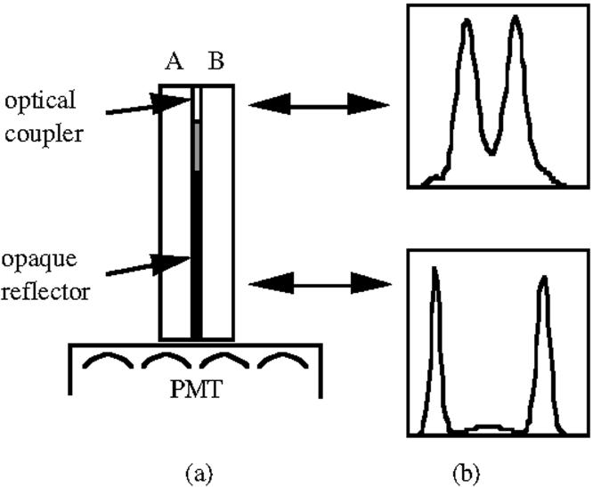
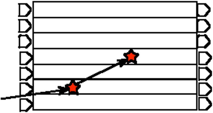
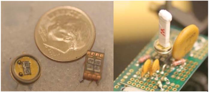
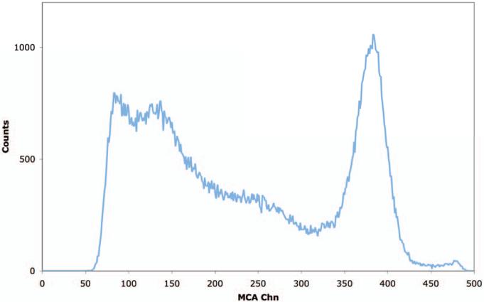
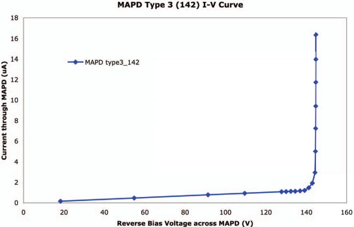
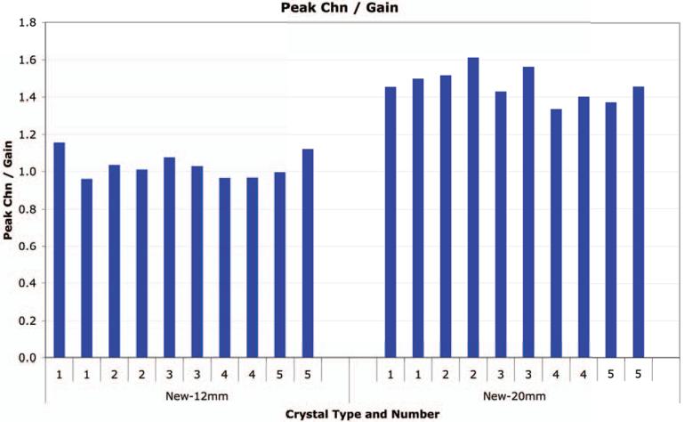
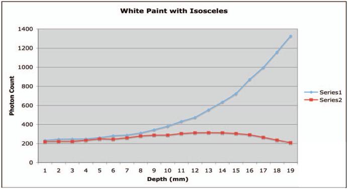
Our laboratory has been developing a depth-of-interaction (DOI) detector design based on light sharing between pairs or quadlets of crystals. Work to date has been utilizing 2×2 mm cross section crystals carefully positioned on a multi-anode PMT. However, there is still significant light sharing in the PMT glass envelope and current PMT designs do not allow one-on-one coupling for arrays of smaller cross section crystals. One-on-one coupling is optimal for implementing the DOI estimator. An alternative to PMTs is to take advantage of progress in fabrication of metal resistive-layer semiconductor photodetectors to provide arrays with one-on-one crystal coupling. We report on our initial tests of one manufacturer's devices. The photodetector (MAPD) and scintillator combination (LFS-3) are both products of Zecotek. The LFS-3 crystal is a variant of LFS that has a better spectral match to the MAPD. Measurements show performance equivalent to or better than that obtained with PMTs and LSO, LFS, or LYSO crystals. For example, 2×2×20 mm crystals are providing 11% energy resolution. The high gain of such devices allow flexibility in designs for both the array and the supporting electronics. We are proceeding with the dMiCE development based on the use of MAPD and LFS-3 arrays.


Figures

Figure 1
Figure 1
dMiCE detector concept. (a) DOI detector unit. (b) PMT ratio plots [A/(A+B)]. A significant amount of light is shared when an event is detected near the entrance face of the detector unit. Less sharing occurs for interactions near the PMT interface
Figure 2
Figure 2
Diagram of the multiple light sources within a detector array due to scatter. The design shown here is for a double sided one-on-one scheme. The main dMiCE design uses only a single ended one-on-one crystal to detector scheme.
Figure 3
Figure 3
Prototype Zecotek Type 3 MAPD arrays. Left are examples of the 1×2 and a 2×2 arrays. Right is a 1×2 array coupled to a pair of LFS-3 crystals.
Figure 4
Figure 4
Measurement circuit for V-I curves
Figure 5
Figure 5
Test circuit for the energy measurements of the individual elements of the prototype MAPD arrays.
Figure 6
Figure 6
Circuit to read out data from two elements simultaneously from a 1×2 prototype MAPD array.
Figure 7
Figure 7
Diagram of the electronics configuration for measurements of MAPD devices and prototype dMiCE detector modules.
Figure 8
Figure 8
Basic geometry of simulations. Light was generated from a single point that was moved along the long axis of the crystal mounted to detector A. The shared surface between the crystals included a reflector that could consist of 3 parts (a rectangle of length R, an isosceles or right triangle of length L that stopped short of the end of the crystal leaving a “gap” of length G.
Figure 9
Figure 9
Typical 511 kEv energy spectrum from a Type 3 MAPD device and a 2×2×12 mm LFS3 crystal. The energy resolution is 11%.
Figure 10
Figure 10
Typical current-voltage curve for a MAPD type 3 device.
Figure 11
Figure 11
Histogram of the relative gains of a Type 3 MAPD with different samples of 2007 production LFS-3 crystals (2×2×12 and 2.2×2.2×20 mm3) with a 500 ns amplifier shaping time.
Figure 12
Figure 12
Plot of detector A (series 1) and detector B (series 2) as a function of depth of a point source of light from the detector. The basic geometry is shown in Figure 8. The shared reflector is an isosceles right triangle (metallic reflector), the unshared crystal sides have a white reflector, and the end cap opposite the detector is a white reflector.
Figure 13
Figure 13
Plot of detector A (series 1) and detector B (series 2) as a function of depth of a point source of light from the detector. The basic geometry is shown in Figure 8. The shared reflector is an isosceles right triangle (metallic reflector), the unshared crystal sides have a metallic reflector, and the end cap opposite the detector is a black absorber.
Figure 14
Figure 14
Plot of the ratio of detector A (series 1) and detector B (series 2) as a function of depth of a point source of light from the detector. The basic geometry is shown in Figure 8. The shared reflector is an isosceles right triangle (metallic reflector), the unshared crystal sides have a metallic reflector, and the end cap opposite the detector is a white reflector. The “error bars” reflect the standard deviations of the data from each detector for 10 simulations at each point source location.
Figure 15
Figure 15
Plot of the ratio of detector A (series 1) and detector B (series 2) as a function of depth of a point source of light from the detector. The basic geometry is shown in Figure 8. The shared reflector is an isosceles right triangle (metallic reflector), the unshared crystal sides have a metallic reflector, and the end cap opposite the detector is a black absorber. The “error bars” reflect the standard deviations of the data from each detector for 10 simulations at each point source location.

References

    1. Lewellen TK, Janes M, Miyaoka RS. Dmice - a Depth-of-Interaction Detector Design for Pet Scanners. Proceedings of the IEEE Nuclear Science Symposium and Medical Imaging Conference; Rome. 2004. pp. 2388–92. - PMC - PubMed
    1. Miyaoka RS, Lewellen TK, Yu H, McDaniel DL. Design of a Depth of Interaction (DOI) Pet Detector Module. IEEE Trans. Nucl. Sci. 1998;45(3):1069–73.
    1. Miyaoka RS, Janes M, Lee KS, Park B, Kinahan PE, Lewellen TK. Development of a Prototype Micro Crystal Element Scanner (Mices): Quickpet II. Molecular Imaging. 2005:117–27. - PubMed
    1. Miyaoka RS, Kohlmyer SG, Lewellen TK. A Second Generation Micro Crystal Element (Mice2) Detector. J. Nucl. Med. 2001:110P. - PubMed
    1. Miyaoka RS, Laymon CM, Janes M, Lee K, Kinahan PE, Lewellen TK. Recent Progress in the Development of a Micro Crystal Element (Mice) Pet System. Proceedings of the 2002 IEEE Nuclear Science Symposium and Medical Imaging Conference; Norfolk. 2002. pp. 1287–91.

LinkOut - more resources