. 2009 Jan;56(1):159-71.
doi: 10.1109/TBME.2008.2005942.

Implantable myoelectric sensors (IMESs) for intramuscular electromyogram recording

Affiliations

Implantable myoelectric sensors (IMESs) for intramuscular electromyogram recording

Richard F ff Weir et al. IEEE Trans Biomed Eng. 2009 Jan.

Abstract

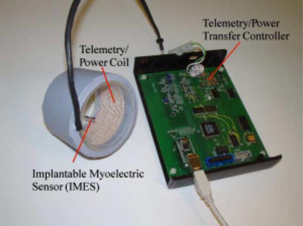
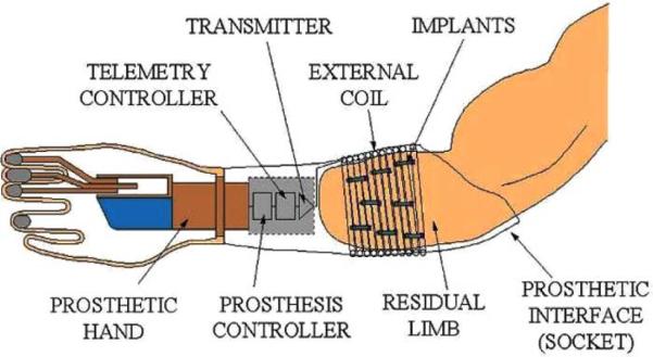
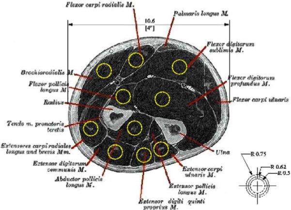
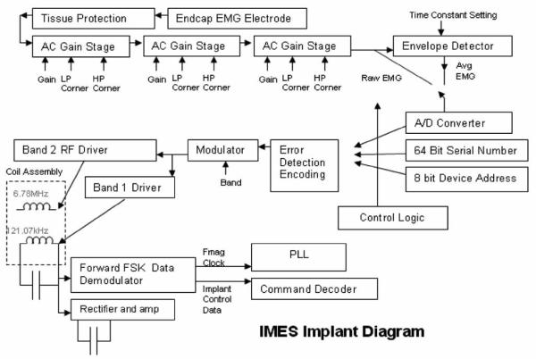
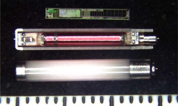
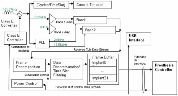
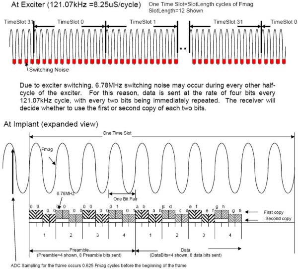
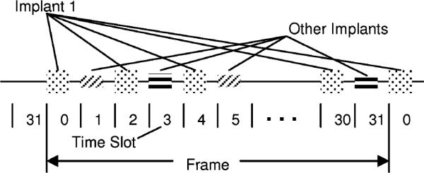
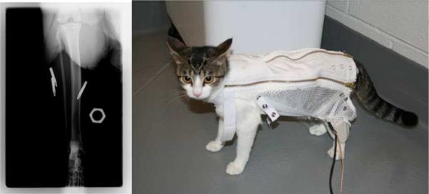
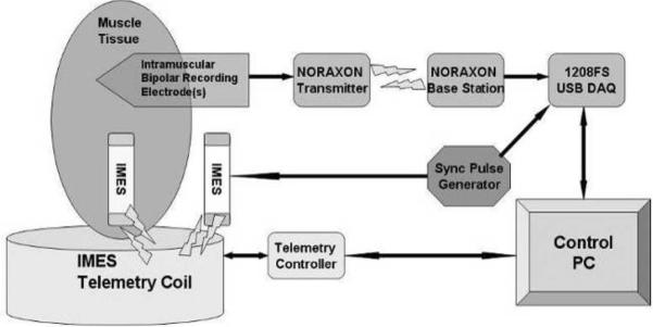
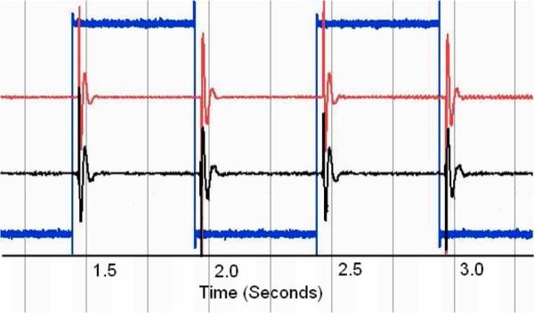
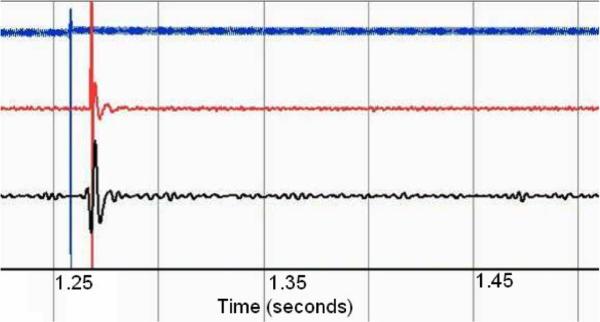
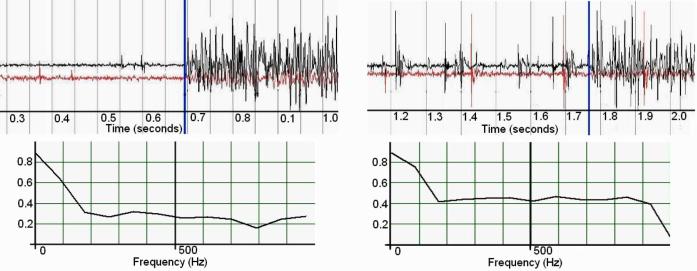
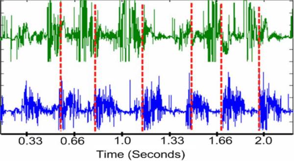
We have developed a multichannel electrogmyography sensor system capable of receiving and processing signals from up to 32 implanted myoelectric sensors (IMES). The appeal of implanted sensors for myoelectric control is that electromyography (EMG) signals can be measured at their source providing relatively cross-talk-free signals that can be treated as independent control sites. An external telemetry controller receives telemetry sent over a transcutaneous magnetic link by the implanted electrodes. The same link provides power and commands to the implanted electrodes. Wireless telemetry of EMG signals from sensors implanted in the residual musculature eliminates the problems associated with percutaneous wires, such as infection, breakage, and marsupialization. Each implantable sensor consists of a custom-designed application-specified integrated circuit that is packaged into a biocompatible RF BION capsule from the Alfred E. Mann Foundation. Implants are designed for permanent long-term implantation with no servicing requirements. We have a fully operational system. The system has been tested in animals. Implants have been chronically implanted in the legs of three cats and are still completely operational four months after implantation.


Figures

Fig. 1
Fig. 1
Photograph of IMES system. The external coil will be laminated directly into the prosthetic interface. Signals from the implants in the arm, linked through the external coil, control the prosthesis via reverse telemetry. Implant power is supplied through the external coil using forward telemetry.
Fig. 2
Fig. 2
Schematic of how IMES, implanted in the muscles of the forearm, communicates via the external coil that is laminated in the prosthetic socket and encircles them when the prosthesis is worn.
Fig. 3
Fig. 3
Projected pickup area for our IMES superimposed on an appropriately scaled section through the proximal forearm. Image shows that pickup area should not be an issue in the final device with each device having a pickup area confined to an individual muscle.
Fig. 4
Fig. 4
IMES implant block diagram.
Fig. 5
Fig. 5
Photograph of IMES components in three assembly states. (Top) IMES silicon chip. (Middle) Sectioned IMES capsule containing IMES subassembly. (Bottom) Completed IMES implant. Shown next to 1 mm scale.
Fig. 6
Fig. 6
Block diagram of telemetry controller. Band 2 reverse telemetry frequency implemented: ISM band, 6.765–6.795 MHz (BW = 30 kHz) 25 μV/m at 300 m (Fc = 6.78 MHz). Identical allocations are present in USA (FCC Part 18) and Europe (EN50081). System supports 32 time slots, 8 cycles/timeslot best-case (10 data bits) = >15.6 ktimeslots/s = >1.9 ksps/implant with eight implants. Required reverse telemetry bandwidth: 502 kHz (BPSK modulation). Required bandwidth exceeds Part 18/EN50081 allocation, acceptable in view of low anticipated emissions. Part 15/EN50081 emission limits for unlicensed intentional radiators: 30 μV/m @ 30 m.
Fig. 7
Fig. 7
Diagram showing the current telemetry data format.
Fig. 8
Fig. 8
Time slot illustration.
Fig. 9
Fig. 9
Implant transmission format—band 1 (60 kHz).
Fig. 10
Fig. 10
Redundant data transmission—band 2 (6.8 MHz).
Fig. 11
Fig. 11
(Right)X-ray of acute IMES implantation. Five-millimeter hexagonal marker used for scale. (Left) Animal wearing jacket and telemetry coil.
Fig. 12
Fig. 12
Acute in vivo experimental schematic diagram.
Fig. 13
Fig. 13
Characteristic normalized (voltage) step response of both systems. Timescale in seconds. Center trace, IMES 2520 sps. Top trace Noraxon 3000 sps. Bottom trace input signal 3000 sps.
Fig. 14
Fig. 14
Characteristic normalized (voltage) impulse response of both systems through tissue. Timescale in seconds. Bottom trace, IMES 2520 sps. Center trace Noraxon 3000 sps. Top trace input signal 3000 sps.
Fig. 15
Fig. 15
Magnitude-squared coherence of IMES vs. noraxon TeleMyo to a 1000-μs pulse through tissue. Nominal frequency bin size 82.2 Hz.
Fig. 16
Fig. 16
Characteristic normalized (voltage) data showing the onset of the crossed extension reflex in the soleus of the acute cat. IMES shown in top. Noraxon shown in bottom. Reflex onset indicated by vertical marker bar.
Fig. 17
Fig. 17
(Left) Intact medial gastrocnemius nerve. (Right) Medial gastrocnemius de-enervated. Both graphs show onset of crossed extension reflex. Normalized (voltage) raw EMG (top) top trace is soleus, bottom trace is medial gastrocnemius. Vertical bar indicates reflex onset. Magnitude-squared coherence (bottom)—on the left is the MSC before denervation, on the right is MSC postdenervation. Nominal frequency bin size 87.9 Hz.
Fig. 18
Fig. 18
Normalized (voltage) characteristic gait cycle data as acquired with the IMES system originally recorded with a maximal peak–peak amplitude of 1.99 mV. 6050 sps. Tibialis anterior on top. Lateral gastrocnemius on bottom. Vertical dashed line is estimate of paw contact.

Similar articles

Cited by

References

    1. Dhillon GS, Horch KW. Direct neural sensory feedback and control of a prosthetic arm. IEEE Trans. Neural Syst. Rehabil. Eng. 2005 Dec.13(no. 4):468–472. - PubMed
    1. Atkins DJ, Heard DCY, Donovan WH. Epidemiologic overview of individuals with upper-limb loss and their reported research priorities. J. Prosthet. Orthot. 1996;8(no. 1):2–11.
    1. Childress DS, Weir RF. Control of limb prostheses. In: Smith DG, Michael JW, Bowker JH, editors. Atlas of Amputations and Limb Deficiencies—Surgical, Prosthetic and Rehabilitation Principles. American Academy of Orthopaedic Surgeons; Rosemont, IL: 2004.
    1. Weir RF. Design of artificial arms and hands for prosthetic applications. In: Kutz M, editor. Standard Handbook of Biomedical Engineering and Design. McGraw-Hill; New York: 2003. pp. 32.1–32.61.
    1. Weir RF, Childress DS. Research trends for the 21st century. In: Meier Robert H., III, Aitkins ODJ., editors. Functional Restoration of Adults and Children with Upper Extremity Amputation. Demos Medical; New York: 2004.

Publication types