. 2009 Jan;36(1):149-63.
doi: 10.1118/1.3021139.

Reducing the sensitivity of IMPT treatment plans to setup errors and range uncertainties via probabilistic treatment planning

Affiliations

Reducing the sensitivity of IMPT treatment plans to setup errors and range uncertainties via probabilistic treatment planning

Jan Unkelbach et al. Med Phys. 2009 Jan.

Abstract

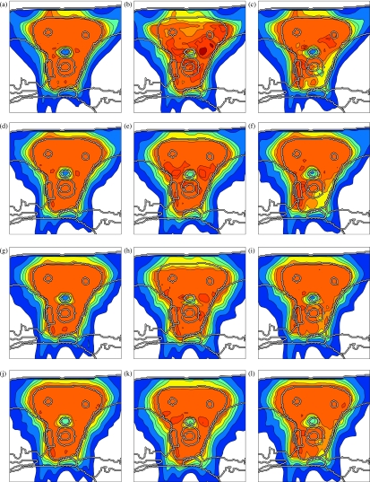
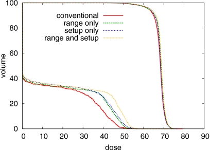
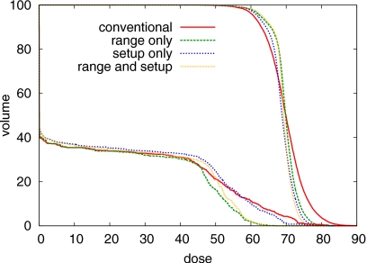
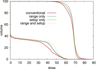
Treatment plans optimized for intensity modulated proton therapy (IMPT) may be very sensitive to setup errors and range uncertainties. If these errors are not accounted for during treatment planning, the dose distribution realized in the patient may by strongly degraded compared to the planned dose distribution. The authors implemented the probabilistic approach to incorporate uncertainties directly into the optimization of an intensity modulated treatment plan. Following this approach, the dose distribution depends on a set of random variables which parameterize the uncertainty, as does the objective function used to optimize the treatment plan. The authors optimize the expected value of the objective function. They investigate IMPT treatment planning regarding range uncertainties and setup errors. They demonstrate that incorporating these uncertainties into the optimization yields qualitatively different treatment plans compared to conventional plans which do not account for uncertainty. The sensitivity of an IMPT plan depends on the dose contributions of individual beam directions. Roughly speaking, steep dose gradients in beam direction make treatment plans sensitive to range errors. Steep lateral dose gradients make plans sensitive to setup errors. More robust treatment plans are obtained by redistributing dose among different beam directions. This can be achieved by the probabilistic approach. In contrast, the safety margin approach as widely applied in photon therapy fails in IMPT and is neither suitable for handling range variations nor setup errors.


Figures

Figure 1
Figure 1
Paraspinal case: The thick contours correspond to the CTV, the spinal cord, and the esophagus.
Figure 2
Figure 2
Sensitivity analysis of a conventional treatment plan: (a) dose distribution that results from a 3.5 mm setup error posteriorly, (b) dose distribution realized for a 3.5 mm setup error anteriorly, (c) color scale for cumulative dose distributions (left) and dose contributions of individual beams (right) in percent of the prescribed dose.
Figure 3
Figure 3
Illustration of the effect of misaligned beams. In this schematic example, three pencil beams hit the patient surface at point A. For a setup shift Δs, the three beams hit the patient surface at different points, and hence, yield a different dose distribution.
Figure 4
Figure 4
Dose contributions of the individual beams for four treatment plans: (a)–(c) conventional IMPT plan, (d)–(f) IMPT plan optimized for range uncertainties alone, (g)–(i) IMPT plan optimized for setup errors alone and (j)–(l) IMPT plan optimized while accounting for both setup and range uncertainty. The color scale in Fig. 2c applies.
Figure 5
Figure 5
Sensitivity analysis of the four treatment plans: (a)–(c) conventional IMPT plan, (d)–(f) IMPT plan optimized for range uncertainties alone, (g)–(i) IMPT plan optimized for setup errors alone, (j)–(l) IMPT plan optimized while accounting for both setup and range uncertainty; the three columns show the nominal dose distribution [(a), (d), (g), (j)], the dose distribution resulting from a systematic overshoot of 5 mm in water equivalent range [(b), (e), (h), (k)], and a systematic setup error of 2.5 mm rightwards [(c), (f), (i), (l)]. The color scale in Fig. 2c applies.
Figure 6
Figure 6
DVH comparison of the four treatment plans for the nominal case, that is no range or setup error occurs. DVHs for the CTV and the spinal cord are shown.
Figure 7
Figure 7
DVH comparison of the four treatment plans for an overshoot of 5 mm in water equivalent range. DVHs for the CTV and the spinal cord are shown.
Figure 8
Figure 8
DVH comparison of the four treatment plans for a setup error of 2.5 mm rightwards. DVHs for the CTV and the spinal cord are shown.
Figure 9
Figure 9
Standard deviation of the dose for three treatment plans discussed in Appendix B: (a) optimized for beamlet correlation model 2, (b) optimized for model 3, (c) conventional plan. The color scale is in percent of prescribed dose.
Figure 10
Figure 10
SDVH comparison for CTV and spinal cord for the treatment plans discussed in Appendix B. The standard deviation of the dose is calculated using correlation model 2.
Figure 11
Figure 11
SDVH comparison for CTV and spinal cord for the treatment plans discussed in Appendix B. The standard deviation of the dose is calculated using correlation model 3.
Figure 12
Figure 12
Illustration of the improved static dose cloud approximation: For a setup error Δs, the entrance point of the pencil beam is shifted by Δc on the patient surface.
Figure 13
Figure 13
Illustration of dose approximation using virtual beamlets: The dose distribution of the “real” beamlet marked by the central dot is approximated by the virtual beamlet marked by the dot at the lower left.
Figure 14
Figure 14
Treatment plan optimized for a Gaussian setup error of 2.5 mm while approximating dose distributions for setup errors by the improved static dose cloud approximation (Appendix C1b): (a)–(c) dose contributions of individual beams, (d) dose distribution for the nominal case, (e) dose distribution for a 2.5 mm setup error rightwards predicted by the improved static dose cloud approximation, and (f) dose distribution for a 2.5 mm setup error rightwards predicted by the virtual bixel approximation method. The color scale in Fig. 2c applies.

References

    1. Schneider U., Pedroni E., and Lomax A., “The calibration of CT Hounsfield units for radiotherapy treatment planning,” Phys. Med. Biol. PHMBA710.1088/0031-9155/41/1/009 41, 111–124 (1996). - DOI - PubMed
    1. Schaffner B. and Pedroni E., “The precision of proton range calculations in proton radiotherapy treatment planning: Experimental verification of the relation between CT HU and proton stopping power,” Phys. Med. Biol. PHMBA710.1088/0031-9155/43/6/016 43, 1579–1592 (1998). - DOI - PubMed
    1. Flampouri S., Slopsema R., Yeung D., Malyapa R., Keole S., Vargas C., and Li Z., “Realistic estimation of proton range uncertainties and dosimetric implications,” Med. Phys. MPHYA6 34(6), 2643 (2007) (abstract).
    1. Jäkel O. and Reiss P., “The influence of metal artefacts on the range of ion beams,” Phys. Med. Biol. PHMBA7 52(3), 653–644 (2007). - PubMed
    1. Unkelbach J., Chan T. C. Y., and Bortfeld T., “Accounting for range uncertainties in the optimization of intensity modulated proton therapy,” Phys. Med. Biol. PHMBA710.1088/0031-9155/52/10/009 52, 2755–2773 (2007). - DOI - PubMed

Publication types

LinkOut - more resources