. 2009 Mar;16(Pt 2):217-25.
doi: 10.1107/S0909049508040612. Epub 2009 Jan 10.

Mini-beam collimator enables microcrystallography experiments on standard beamlines

Affiliations

Mini-beam collimator enables microcrystallography experiments on standard beamlines

Robert F Fischetti et al. J Synchrotron Radiat. 2009 Mar.

Abstract

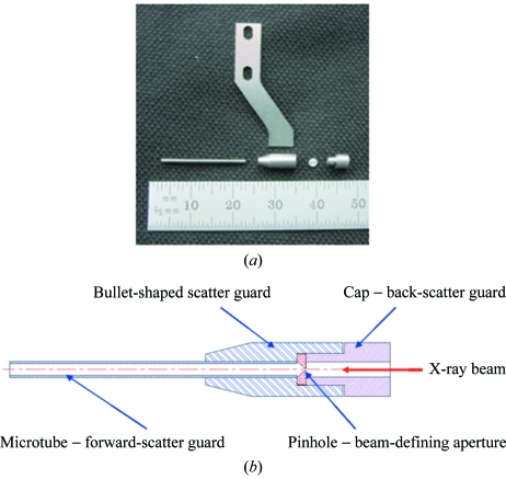
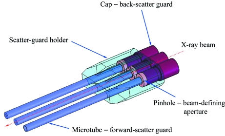
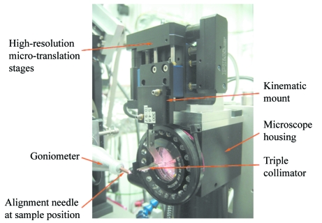
The high-brilliance X-ray beams from undulator sources at third-generation synchrotron facilities are excellent tools for solving crystal structures of important and challenging biological macromolecules and complexes. However, many of the most important structural targets yield crystals that are too small or too inhomogeneous for a ;standard' beam from an undulator source, approximately 25-50 microm (FWHM) in the vertical and 50-100 microm in the horizontal direction. Although many synchrotron facilities have microfocus beamlines for other applications, this capability for macromolecular crystallography was pioneered at ID-13 of the ESRF. The National Institute of General Medical Sciences and National Cancer Institute Collaborative Access Team (GM/CA-CAT) dual canted undulator beamlines at the APS deliver high-intensity focused beams with a minimum focal size of 20 microm x 65 microm at the sample position. To meet growing user demand for beams to study samples of 10 microm or less, a ;mini-beam' apparatus was developed that conditions the focused beam to either 5 microm or 10 microm (FWHM) diameter with high intensity. The mini-beam has a symmetric Gaussian shape in both the horizontal and vertical directions, and reduces the vertical divergence of the focused beam by 25%. Significant reduction in background was achieved by implementation of both forward- and back-scatter guards. A unique triple-collimator apparatus, which has been in routine use on both undulator beamlines since February 2008, allows users to rapidly interchange the focused beam and conditioned mini-beams of two sizes with a single mouse click. The device and the beam are stable over many hours of routine operation. The rapid-exchange capability has greatly facilitated sample screening and resulted in several structures that could not have been obtained with the larger focused beam.


Figures

Figure 1
Figure 1
Components of the mini-beam collimator. (a) Exploded view of the mini-beam collimator and support. The direction of beam travel through the components is from right to left. The collimator components are the Mo back-scatter guard (positioned at the 46 mm mark on the ruler), the beam-defining Pt pinhole (39 mm), the bullet-shaped scatter guard (30 mm) and the forward-scatter guard tube (12 mm). The pinhole is on its side in this picture for clarity. The stainless steel arm (above the collimator components) connects the assembled collimator to the kinematic carrier (Fig. 2 ▶). (b) Schematic diagram of the assembled mini-beam collimator. Excellent scatter protection is achieved by nesting of the pinhole, back-scatter guard and forward-scatter tube inside the bullet-shaped scatter guard.
Figure 2
Figure 2
Schematic diagram of the triple collimator. Each collimator consists of a beam-defining pinhole, a forward-scatter tube and a back-scatter guard. These are mounted in a three-way Mo scatter guard.
Figure 3
Figure 3
Kinematic mounting of the mini-beam collimator. (a) Assembled mini-beam collimator on an exchangeable kinematic carrier, with the halves of the black-anodized Al kinematic mount separated showing details of the mount. The kinematic base is attached to an alignment jig. (b) Mini-beam apparatus mounted on the alignment jig. The two halves of the kinematic mount are mated. The bullet-shaped scatter guard and forward-scatter guard tube of the collimator are positioning in the alignment groves. The small sapphire ball at the end of the forward-scatter guard tube was attached only during metrology measurements. The pinhole and back-scatter guard are not shown.
Figure 4
Figure 4
Mini-beam apparatus mounted in the experimental station of beamline 23ID-B. The photograph shows the relationship of the mini-beam positioning motors to the housing for the high-resolution on-axis sample-viewing microscope. An alignment needle is mounted on the sample goniometer at the sample position. The photograph also shows the relationship between the mini-beam collimator and the microscope lens, which are separated by ∼0.5 mm.
Figure 5
Figure 5
Effect of slit setting on beam size at the sample position in the (a) vertical and (b) horizontal directions. The slits were 230 mm upstream of the sample position. The beam size was recorded at the sample position using a knife-edge scan as described in the text. The minimum setting of the slits was 13 µm, but beams of this size were not achievable at the sample position when the slits defined the beam. In contrast, the mini-beam size is almost constant over a wide range of upstream slit settings for beams defined by the 5 µm and 10 µm mini-beam collimators.
Figure 6
Figure 6
Profiles of the mini-beam defined by the 5 µm aperture in the vertical (a) and horizontal (b) directions. Profiles were recorded at the sample position using a knife-edge scan as described in the text. The raw knife-edge scans were differentiated, providing the beam profile (solid line). An error function was fit to the raw data (not shown). The best-fit Gaussian is derived from the derivative of the error function (dashed line).
Figure 7
Figure 7
Vertical angular dispersion of the mini-beam. Rocking curves of a Si(220) analyzer crystal located at the sample position were recorded for the full beam (solid line) and for the mini-beam defined by the 10 µm aperture (dashed line).

References

    1. Cherezov, V., Rosenbaum, D. M., Hanson, M. A., Rasmussen, S. G., Thian, F. S., Kobilka, T. S., Choi, H. J., Kuhn, P., Weis, W. I., Kobilka, B. K. & Stevens, R. C. (2007). Science, 318, 1258–1265. - PMC - PubMed
    1. Cipriani, F., Felisaz, F., Lavault, B., Brockhauser, S., Ravelli, R., Launer, L., Leonard, G. & Renier, M. (2007). Ninth International Conference on Synchrotron Radiation Instrumentation, edited by J.-Y. Choi and S. Rah, pp. 1928–1931. New York: American Institute of Physics.
    1. Coulibaly, F., Chiu, E., Ikeda, K., Gutmann, S., Haebel, P. W., Schulze-Briese, C., Mori, H. & Metcalf, P. (2007). Nature (London), 446, 97–101. - PubMed
    1. Decker, G. & Singh, O. (2005). Proceedings of the 2005 Particle Accelerator Conference, Knoxville, TN, USA, pp. 3268–3270 (http://www.jacow.Org/p05/papers/rpae053.pdf).
    1. Fischetti, R. F., Yoder, D. W., Xu, S., Stepanov, S., Makarov, O., Benn, R., Corcoran, S., Diete, W., Schwörer-Böhing, M., Signorato, R., Schröder, L., Berman, L., Viccaro, P. J. & Smith, J. L. (2007). Ninth International Conference on Synchrotron Radiation Instrumentation, edited by J.-Y. Choi and S. Rah, pp. 754–757. New York: American Institute of Physics.

Publication types

MeSH terms