. 2009 Feb 27;33(4):528-36.
doi: 10.1016/j.molcel.2009.01.035.

Alternating access in maltose transporter mediated by rigid-body rotations

Affiliations

Alternating access in maltose transporter mediated by rigid-body rotations

Dheeraj Khare et al. Mol Cell. .

Abstract

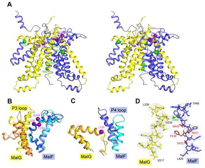
ATP-binding cassette transporters couple ATP hydrolysis to substrate translocation through an alternating access mechanism, but the nature of the conformational changes in a transport cycle remains elusive. Previously we reported the structure of the maltose transporter MalFGK(2) in an outward-facing conformation in which the transmembrane (TM) helices outline a substrate-binding pocket open toward the periplasmic surface and ATP is poised for hydrolysis along the closed nucleotide-binding dimer interface. Here we report the structure of the nucleotide-free maltose transporter in which the substrate binding pocket is only accessible from the cytoplasm and the nucleotide-binding interface is open. Comparison of the same transporter crystallized in two different conformations reveals that alternating access involves rigid-body rotations of the TM subdomains that are coupled to the closure and opening of the nucleotide-binding domain interface. The comparison also reveals that point mutations enabling binding protein-independent transport line dynamic interfaces in the TM region.


Figures

Figure 1
Figure 1. Functional Assay of the ΔTM1 construct
(A) Maltose transport was analyzed on MacConkey plates in a strain carrying a Tn10 insertion in malF (see Experimental Procedures). A red color indicates that maltose is transported. An empty vector was used as a negative control. (B) MBP-stimulated ATPase activity of purified MalFGK2 reconstituted into proteoliposomes (see Experimental Procedures). Each bar shows the average and standard deviation of 3 to 4 independent measurements.
Figure 2
Figure 2. Alternating access in the maltose transporter
Ribbon diagram (left) and a 12-Å slab view (right) of the maltose transporter in (A) the inward-facing, resting state conformation and (B) the outward-facing, catalytic intermediate conformation (Oldham et al., 2007). The maltose and ATP are shown in CPK and ball-and-stick models, respectively.
Figure 3
Figure 3. Conformational changes in the transmembrane subunits
(A) The architecture of MalG (yellow) and MalF (blue) in the inward-facing conformation, viewed along the membrane normal from the cytoplasm. Helices in the core and peripheral regions are shown in ribbon and cylinder representations, respectively. Residues constituting the periplasmic gate are shown in red. The two gray masks specify helices that move in concert during the structural transition. (B) Superposition of MalG (left) and MalF (right) as they occur in the resting and transition-state conformations. Residues involved in maltose binding are specified by red dots. (C) Cartoon showing the translocation pathway in the resting and (D) the transition states. The location of maltose in the outward-facing conformation is indicated by a red star. Gating loops are shown in red. The two coupling helices, also known as EAA loops of MalG and MalF, are labeled by “EAA” and “EAS”, respectively, based on their sequence. (E) Stereoview of the TM cores, the inward- and outward facing structures are superimposed based on the MalK regulatory domains. The grey lines indicate the two rotation axes relative to the regulatory domains. Color codes: MalG resting state, yellow, transition state, orange; MalF resting state, blue, transition state, cyan.
Figure 4
Figure 4. Conformational changes in the MalK subunits
Ribbon diagram of the MalK (A) open dimer in the inward-facing structure and (B) closed dimer in the outward-facing structure. The two NBDs are colored in green and red and the regulatory domains are colored in grey. The helical subdomains are indicated and colored in light green or red. The Walker A (WA) and the LSGGQ motifs are colored in blue and yellow, respectively. ATP is shown in stick models. (C) Stereo-diagram of MalK in the resting state. Using the regulatory domains (grey) as the frame of reference, rotations of the two NBDs (green and red) leading to the closed dimer are indicated.
Figure 5
Figure 5. Rigid body rotations that mediate alternating access
(A) Stereoview of the maltose transporter in the inward-facing conformation with rotation axes indicated (color codes are consistent with those of the protein subunits). (B) Stereoview of the outward-facing structure (regions that are not observed in the inward-facing structure are omitted). The rotation axes of the helical subdomains are not shown.
Figure 6
Figure 6. Conformational change at the MalK/TMD interface
The structures are superpositioned based on the RecA-like subdomains of MalK. The NBDs of MalK from the inward- and outward-facing structures are shown in green and grey, respectively. MalG is rendered in yellow (resting state) and orange (transition state). The coupling helix is labeled as “EAA loop”.
Figure 7
Figure 7. The binding-protein independent mutants
(A) Stereoview of MalFG in the resting state showing the positions of mutations that enable transport without MBP (Covitz et al., 1994). The p-site mutations (L334W, F336L, and G338R) of MalF and MalG L135F are shown in magenta. The second-site mutations (MalF W378C, V442A, A502V, N505I, and MalG I154S) are shown in green. (B) A close-up view of the p-site interaction with MalG. (C) Interactions of MalG L135 and MalF. (D) Contacts between MalF V442 and MalG V230, together with σA-weighted phased-combined 2Fo-Fc electron density maps with a B-factor sharpening factor of -140 Å2 contoured at 1 σ. Maltose-binding residues are shown in red. Color identification is as in Fig 3.

References

    1. Abrahams JP, Leslie AG. Methods used in the structure determination of bovine mitochondrial F1 ATPase. Acta Crystallogr D Biol Crystallogr. 1996;52:30–42. - PubMed
    1. Abramson J, Smirnova I, Kasho V, Verner G, Kaback HR, Iwata S. Structure and mechanism of the lactose permease of Escherichia coli. Science. 2003;301:610–615. - PubMed
    1. Austermuhle MI, Hall JA, Klug CS, Davidson AL. Maltose-binding protein is open in the catalytic transition state for ATP hydrolysis during maltose transport. J Biol Chem. 2004;279:28243–28250. - PubMed
    1. Brunger AT. Version 1.2 of the Crystallography and NMR system. Nat Protoc. 2007;2:2728–2733. - PubMed
    1. Chen J, Lu G, Lin J, Davidson AL, Quiocho FA. A tweezers-like motion of the ATP-binding cassette dimer in an ABC transport cycle. Mol Cell. 2003;12:651–661. - PubMed

Publication types

MeSH terms

Substances

Associated data