. 2009 Apr;6(2):026002.
doi: 10.1088/1741-2560/6/2/026002. Epub 2009 Mar 2.

A fully implantable 96-channel neural data acquisition system

Affiliations

A fully implantable 96-channel neural data acquisition system

Michael Rizk et al. J Neural Eng. 2009 Apr.

Abstract

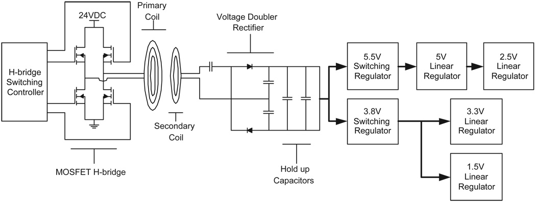
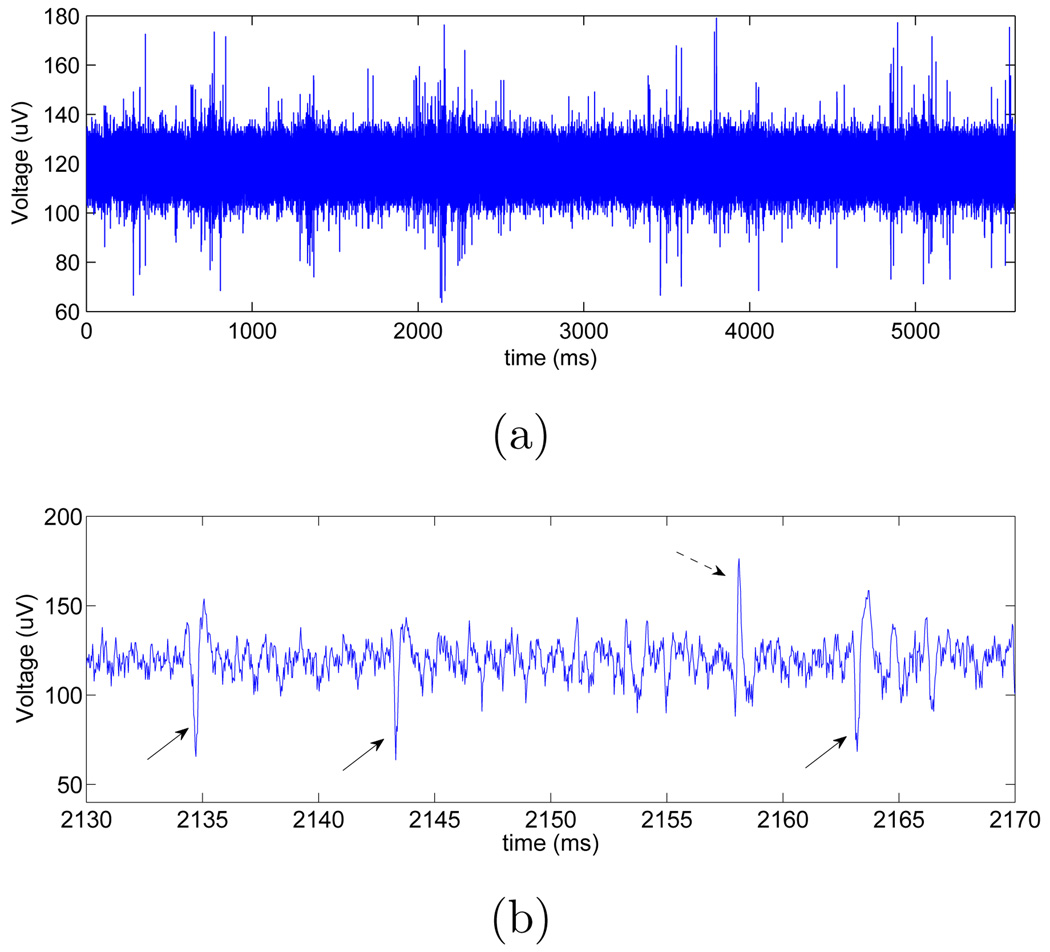
A fully implantable neural data acquisition system is a key component of a clinically viable brain-machine interface. This type of system must communicate with the outside world and obtain power without the use of wires that cross through the skin. We present a 96-channel fully implantable neural data acquisition system. This system performs spike detection and extraction within the body and wirelessly transmits data to an external unit. Power is supplied wirelessly through the use of inductively coupled coils. The system was implanted acutely in sheep and successfully recorded, processed and transmitted neural data. Bidirectional communication between the implanted system and an external unit was successful over a range of 2 m. The system is also shown to integrate well into a brain-machine interface. This demonstration of a high channel-count fully implanted neural data acquisition system is a critical step in the development of a clinically viable brain-machine interface.


Figures

Figure 1
Figure 1
Block diagram of the neural data acquisition system. Figure adapted with permission from [12].
Figure 2
Figure 2
The digitizing headstage module circuit board. This board contains two custom integrated circuits (each responsible for amplifying 16 channels), two analog-to-digital converters (ADCs), and a complex programmable logic device (CPLD). Neural signals picked up by the electrodes are amplified, filtered, and digitized before being passed on to the implantable central communications module (ICCM) for further processing. The connector on the right side of the figure is optional.
Figure 3
Figure 3
Block diagram of the custom integrated-circuit amplifiers. The extracellular potential sensed by the probe is amplified to a magnitude appropriate for the ADC. Signals outside the frequency band of extracellular potentials are removed by a switched-capacitor filter. The multiplexer directs a different channel to the ADC every two microseconds.
Figure 4
Figure 4
Drawing of the custom integrated-circuit amplifiers. The pads that connect to the neural probes are along the left edge. The amplifiers for each channel are in the repeating horizontal pattern that spans almost the entire chip. The digital-to-analog converters are in the lower left. The differential amplifier is in the lower right.
Figure 5
Figure 5
The implantable central communications module (ICCM) circuit board. The arrows indicate the neural signal processor FPGA and the transceiver. An identical board is used for the wireless communications module (WCM). Figure used with permission from [12].
Figure 6
Figure 6
Diagram of the transcutaneous energy transfer system (TETS) used to power the implanted system. A commercially available H-bridge controller switches on anti-parallel pairs of MOSFETs in the H-bridge inverter. The externally worn primary coil energizes the implanted secondary coil through linked magnetic flux. The step-up winding scheme and voltage doubler rectifier ensure that the input voltage to the switching regulators is well above the dropout voltage.
Figure 7
Figure 7
Neural data recorded percutaneously from an owl monkey. (a) Fifty milliseconds of streaming data from a single channel. At the right are the two spike waveforms extracted by our system. (b) Spikes extracted by our system from several channels over a roughly one-minute period.
Figure 8
Figure 8
The implantable portions of the neural data acquisition system packaged for implantation. The reference temperature probe and the DC power-in cable were used for evaluation purposes and are not required for the system to be functional. The system shown here was implanted in a sheep.
Figure 9
Figure 9
(a) Streaming neural data recorded by our system while it was fully implanted in a sheep. (b) A zoomed-in portion of some of the data. The three solid arrows point to spikes that presumably came from a neuron near this particular channel’s electrode. The dashed arrow points to a spike that presumably came from a neuron near the reference electrode.
Figure 10
Figure 10
Spikes extracted from several channels while the system was fully implanted in a sheep. These spikes were extracted by our system from selected channels over a roughly one-minute period. Extractions occurring on the positive threshold have been removed for the first 4 channels. For the remaining channels, all spikes extracted by the system are shown. These last 16 channels all shared a common reference electrode, and the majority of extractions are presumably due to neural activity near the reference electrode. For the boxed channel, spikes were extracted due to activity near the reference electrode and due to activity near the channel’s electrode. The boxed channel is the channel for which streaming data is shown in figure 9.
Figure 11
Figure 11
The external components of the neural data acquisition system. The adapter allows the WCM to plug into the data acquisition card installed in the laptop computer.
Figure 12
Figure 12
Flow of information in the BMI setup. (A) Current direction of motion is determined based on either the predetermined trajectory or the “joystick” input. (B) Instantaneous firing rates are computed based on tuning curves and then spike times are generated. (C) Analog waveforms are constructed based on the spike times and then sent to the neural data acquisition system. (D) The neural data acquisition system performs spike detection (and possibly spike sorting) and outputs 50-ms bin counts. (E) The bin counts are sent to a decoder that maps the bin counts to a direction in real time. (F) The estimated trajectory is updated in real time based on the estimate of the current direction. The reconstructed trajectory on the left in (F) can be seen to match the predetermined (i.e., true) trajectory on the left in (A) quite well. For real-time estimation of a joystick-controlled trajectory, fairly good control of the estimated trajectory (seen on the right in (F)) can be achieved. Our ability to write “duke” is evidence of this. The joystick is seen on the right in (A).

References

    1. Serruya MD, Hatsopoulos NG, Paninski L, Fellows MR, Donoghue JP. Instant neural control of a movement signal. Nature. 2002 Mar;416(6877):141–142. - PubMed
    1. Taylor DM, Tillery SI, Schwartz AB. Direct cortical control of 3d neuroprosthetic devices. Science. 2002 Jun;296(5574):1829–1832. - PubMed
    1. Carmena JM, Lebedev MA, Crist RE, O’Doherty JE, Santucci DM, Dimitrov DF, Patil PG, Henriquez CS, Nicolelis MA. Learning to control a brain-machine interface for reaching and grasping by primates. PLoS Biol. 2003 Nov;1(2):193–208. - PMC - PubMed
    1. Kennedy PR, Bakay RAE, Moore MM, Adams K, Goldwaithe J. Direct control of a computer from the human central nervous system. IEEE Trans Rehabil Eng. 2000 Jun;8(2):198–202. - PubMed
    1. Patil PG, Carmena JM, Nicolelis MAL, Turner DA. Ensemble recordings of human subcortical neurons as a source of motor control signals for a brain-machine interface. Neurosurgery. 2004 Jul;55(1):27–38. - PubMed

Publication types