. 2009 Apr 17;381(4):712-6.
doi: 10.1016/j.bbrc.2009.02.133. Epub 2009 Mar 1.

Structural and functional studies on the stalk of the transferrin receptor

Affiliations

Structural and functional studies on the stalk of the transferrin receptor

Danijela Dukovski et al. Biochem Biophys Res Commun. .

Abstract

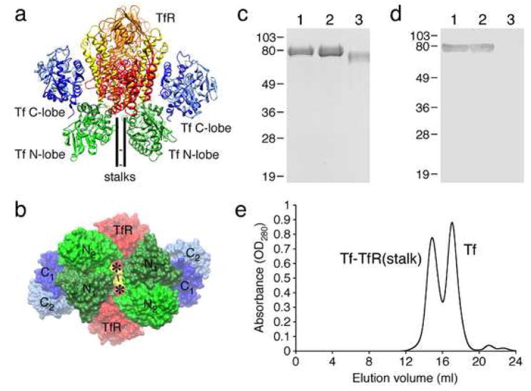
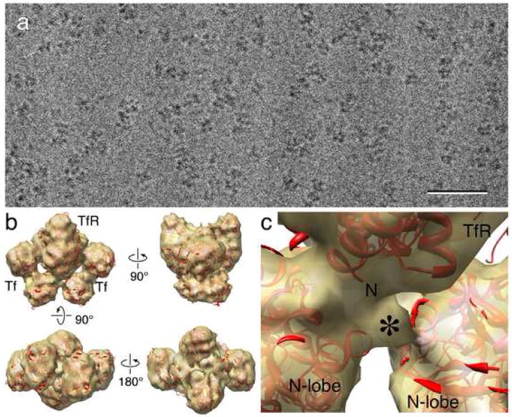
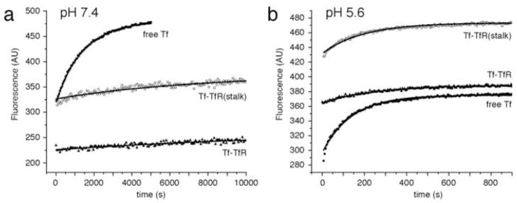
Transferrin (Tf) is an iron carrier protein that consists of two lobes, the N- and C-lobes, which can each bind a Fe(3+) ion. Tf binds to its receptor (TfR), which mediates iron delivery to cells through an endocytotic pathway. Receptor binding facilitates iron release from the Tf C-lobe, but impedes iron release from the N-lobe. An atomic model of the Tf-TfR complex based on single particle electron microscopy (EM) indicated that receptor binding is indeed likely to hinder opening of the N-lobe, thus interfering with its iron release. The atomic model also suggested that the TfR stalks could form additional contacts with the Tf N-lobes, thus potentially further slowing down its iron release. Here, we show that the TfR stalks are unlikely to make strong interactions with the Tf N-lobes and that the stalks have no effect on iron release from the N-lobes of receptor-bound Tf.


Figures

Fig. 1
Fig. 1
The Tf-TfR(stalk) complex. (a) Atomic model of the Tf-TfR complex in ribbon representation (pdb id: 1SUV) based on a single particle EM reconstruction [6]. (b) Atomic model of the Tf-TfR complex in space filling representation showing the gap between the two Tf N-lobes through which the TfR stalks must pass. The asterisks indicate the putative positions of the TfR stalks and the lines the disulfide bridges between the two stalks. (c) 12.5% SDS PAGE gel of TfR(stalk) (lane 1), Tf-TfR(stalk) complex (lane 2), and stalk-less TfR (lane 3). (d) Western blot of the gel shown in (a) developed with anti-His antibody. (e) Elution profile from a size exclusion column showing two peaks corresponding to the Tf-TfR(stalk) complex and free Tf.
Fig. 2
Fig. 2
Cryo-electron microscopy of the Tf-TfR(stalk) complex. (a) Raw image of Tf-TfR(stalk) complex in vitrified ice. Scale bar is 50 nm. (b) Four views of the density map of the Tf-TfR(stalk) complex (gold) with the fit atomic model of the complex (red). (c) Close-up view of the density (asterisk) that may represent the beginning of the TfR stalk. The “N” indicates the beginning of the stalk-less construct used to determine the crystal structure of TfR.
Fig. 3
Fig. 3
Negative stain EM of Tf complexes formed with TfR(stalk) and stalk-less TfR. (a) Class averages obtained by classifying 9381 particles into 100 classes showing predominantly top views of the His-tagged Tf-TfR(stalk) complex adsorbed to a lipid monolayer containing 2% Ni-NTA lipids. (b) Angular distribution plot showing the orientations of the His-tagged Tf-TfR(stalk) complex adsorbed to the lipid monolayer. (c) Class averages obtained by classifying 20,483 particles into 100 classes showing predominantly side views of the stalk-less Tf-TfR complex adsorbed to a continuous carbon film. (d) Angular distribution plot showing the orientations of the stalk-less Tf-TfR(stalk) complex adsorbed to carbon film. Note the difference in the angular distribution compared to panel c.
Fig. 4
Fig. 4
Kinetics of iron release from the Tf N-lobe. (a) Iron release at pH 7.4 from the N-lobe of free TfNFe (squares), TfNFe bound to stalk-less TfR (triangles), and TfNFe bound to TfR(stalk) (circles). (b) Iron release at pH 5.6 from the N-lobe of free TfNFe (squares), TfNFe bound to stalk-less TfR (triangles), and TfNFe bound to TfR(stalk) (circles). Each condition was repeated three times with two different preparations. The data points represent an individual experiment, while the lines show the fitted curves to all six experiments performed for each condition.

References

    1. Baker EN. Structure and reactivity of transferrins. Adv Inorg Chem. 1994;41:389–463.
    1. Baker HM, Anderson BF, Baker EN. Dealing with iron: common structural principles in proteins that transport iron and heme. Proc Natl Acad Sci U S A. 2003;100:3579–3583. - PMC - PubMed
    1. Aisen P. Transferrin receptor 1. Int J Biochem Cell Biol. 2004;36:2137–2143. - PubMed
    1. Lawrence CM, Ray S, Babyonyshev M, Galluser R, Borhani DW, Harrison SC. Crystal structure of the ectodomain of human transferrin receptor. Science. 1999;286:779–782. - PubMed
    1. Jing SQ, Trowbridge IS. Identification of the intermolecular disulfide bonds of the human transferrin receptor and its lipid-attachment site. EMBO J. 1987;6:327–331. - PMC - PubMed

Publication types

LinkOut - more resources