. 2009 Mar 21;54(6):1757-71.
doi: 10.1088/0031-9155/54/6/023. Epub 2009 Mar 3.

Continuous depth-of-interaction encoding using phosphor-coated scintillators

Affiliations

Continuous depth-of-interaction encoding using phosphor-coated scintillators

Huini Du et al. Phys Med Biol. .

Abstract

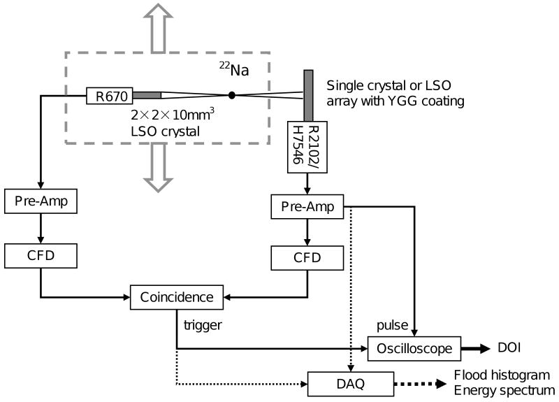
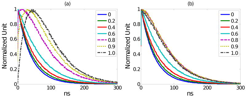
We investigate a novel detector using a lutetium oxyorthosilicate (LSO) scintillator and YGG (yttrium-aluminum-gallium oxide:cerium, Y(3)(Al,Ga)(5)O(12):Ce) phosphor to construct a detector with continuous depth-of-interaction (DOI) information. The far end of the LSO scintillator is coated with a thin layer of YGG phosphor powder which absorbs some fraction of the LSO scintillation light and emits wavelength-shifted photons with a characteristic decay time of approximately 50 ns. The near end of the LSO scintillator is directly coupled to a photodetector. The photodetector detects a mixture of the LSO light and the light emitted by YGG. With appropriate placement of the coating, the ratio of the light converted from the YGG coating with respect to the unconverted LSO light can be made to depend on the interaction depth. DOI information can then be estimated by inspecting the overall light pulse decay time. Experiments were conducted to optimize the coating method. 19 ns decay time differences across the length of the detector were achieved experimentally when reading out a 1.5 x 1.5 x 20 mm(3) LSO crystal with unpolished surfaces and half-coated with YGG phosphor. The same coating scheme was applied to a 4 x 4 LSO array. Pulse shape discrimination (PSD) methods were studied to extract DOI information from the pulse shape changes. The DOI full-width-half-maximum (FWHM) resolution was found to be approximately 8 mm for this 2 cm thick array.


Figures

Figure 1
Figure 1
Concept for a continuous DOI scintillation detector. The light reaching the photodetector is a mixture of direct scintillation light, and scintillation light that has been absorbed and re-emitted by the phosphor. The pulse-shape therefore depends on the relative contribution of the scintillation and phosphor light. If the fraction of phosphor-converted light can be made depth-dependent, pulse-shape analysis can yield information on the depth of interaction.
Figure 2
Figure 2
(a) Measured excitation spectrum of YGG:Ce and emission spectrum of LSO:Ce; (b) Measured emission spectrum of YGG:Ce
Figure 3
Figure 3
Illustration of four different schemes to coat a single LSO crystal with YGG:Ce phosphor. Phosphor coating is ∼0.25 mm thick and is shown in green.
Figure 4
Figure 4
Experimental set-up
Figure 5
Figure 5
(a) and (b) pictures of 4 by 4 LSO array coated with YGG:Ce phosphor (End + ½ Sides) and (c) a flood histogram by irradiating the LSO-YGG array uniformly. Outer layer of Teflon tape reflector has been removed to show phosphor coating.
Figure 6
Figure 6
Five PSD methods (a) Constant Fraction Discrimination (b) Rise Time Discrimination (c) Constant Time Discrimination (d) Charge Comparison (e) Delayed Charge Integration
Figure 7
Figure 7
Quantum efficiency spectra for three different photodetectors: MC-PMT H7546-M64, APD, and MPPC S10362-11-025. The MPPC data is expressed in terms of the photodetection efficiency, accounting for the non-unity fill factor of MPPC's as well as the quantum efficiency.
Figure 8
Figure 8
Averaged pulse shape at three different depths: 3, 10 and 17 mm with (a) “No Coating” (b) “End + 1/2 Sides” coating.
Figure 9
Figure 9
Flood histograms of the LSO-YGG array for irradiation depths of 2, 6, 10, 14, and 18 mm
Figure 10
Figure 10
Energy histograms obtained at five irradiation depths.
Figure 11
Figure 11
Histograms of DOI parameter calculated by DCI method when 2 cm crystal length is segmented into 2, 3, 4 or 5 bins and array is irradiated with a ∼2 mm wide beam at the center of each depth bin.
Figure 12
Figure 12
Peak of DOI parameter histograms versus known irradiation depth with linear fit superimposed.
Figure 13
Figure 13
(a) Simulated pulses detected by PMT with light conversion ratios of 0, 0.2, 0.4, 0.6, 0.8, 0.9 and 1.0. (b) Same data with peaks aligned in time to better illustrate changes in fall time of the pulses.
Figure 14
Figure 14
(a) Simulated pulses detected by PMT, APD and MPPC (with QE taken from Figure 7) when there is 50% LSO light and 50% YGG-converted light; (b) Changes in DCI value as a function of the converted light ratio (DCI calculated with W=120ns, D=60ns).

Similar articles

Cited by

References

    1. Chandrikamohan P, DeVol TA. Comparison of Pulse Shape Discrimination Methods for Phoswich and CsI:Tl Detectors. IEEE Trans Nucl Sci. 2007;54:398–403.
    1. Du H, Yang Y, Cherry SR. Measurements of wavelength shifting (WLS) fibre readout for a highly multiplexed, depth-encoding PET detector. Phys Med Biol. 2007;52:2499–514. - PubMed
    1. Du H, Yang Y, Cherry SR. Comparison of four depth-encoding PET detector modules with wavelength shifting (WLS) and optical fiber read-out. Phys Med Biol. 2008;53:1829–42. - PMC - PubMed
    1. Judenhofer MS, Pichler BJ, Cherry SR. Evaluation of high performance data acquisition boards for simultaneous sampling of fast signals from PET detectors. Phys Med Biol. 2005;50:29–44. - PubMed
    1. Liu H, Omura T, Watanabe M, Yamashita T. Development of a depth of interaction detector for [gamma]-rays. Nucl Instrum Methods A. 2001;459:182–90.

Publication types