Review
. 2009 May-Jun;38(3):135-43.
doi: 10.1067/j.cpradiol.2007.10.001.

Radiofrequency and microwave ablation of the liver, lung, kidney, and bone: what are the differences?

Affiliations
Review

Radiofrequency and microwave ablation of the liver, lung, kidney, and bone: what are the differences?

Christopher L Brace. Curr Probl Diagn Radiol. 2009 May-Jun.

Abstract

Radiofrequency (RF) ablation is becoming an accepted treatment modality for many tumors of the liver and is being explored for tumors in the lung, kidney, and bone. While RF energy is the most familiar heat source for tissue ablation, it has certain limitations that may hamper its efficacy in these new organ systems. Microwave energy may be a better source for tissue ablation but has technical hurdles that must be overcome as well. This article outlines the physics behind RF and microwave heating, discusses relevant properties of the liver, lung, kidney, and bone for thermal ablation and examines the roles of RF and microwave ablation in these tissues.


Figures

Figure 1
Figure 1
Simulated initial current densities of RF ablation in monopolar (left) and bipolar (right) modes. Contour maps indicate electric field isocontours and arrows indicate current density within each inset. Monopolar mode tends to disperse current more freely, while bipolar mode creates high current densities that are confined between electrodes.
Figure 2
Figure 2
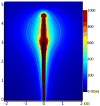
Heating pattern around a triaxial microwave ablation antenna. Note that the zone of active heating is nearly 2 cm in diameter and no ground pads are needed. This larger zone of heating results in better performance near blood vessels and improved multiple-antenna capabilities.
Figure 3
Figure 3
Simulated heating profiles of arrays using a) two, b) three, c) four and d) six antennas. The heat generation rate at the center of the array is improved by a factor of a) four, b) nine, c) 16 and d) 36 over a single antenna by using constructive antenna phasing.
Figure 4
Figure 4
Images of perivascular ablations created using RF (left) and microwave (right) energy. Both ablations were created using a three-applicator system in normal swine liver. Applicator locations are marked with an ‘X’. The large vessel (arrow) prevented conglomeration of the RF ablation zone, despite the close proximity of all three electrodes. By contrast, the microwave ablation extends around and beyond a large vessel (arrow) despite being at the normal ablation zone periphery.
Figure 5
Figure 5
Approximation of impedance versus temperature during RF ablation. As temperature approaches 100 C, water tends to boil off, causing a rapid increase in impedance as “seen” by the generator. This increase inhibits current flow and substantially reduces heat generation.
Figure 6
Figure 6
Temperatures recorded during RF and microwave ablation illustrating the faster heating and higher temperatures achievable with microwave energy. The RF system included a 17-gauge cooled electrode and 200 W generator using an impedance-feedback algorithm (Valleylab), while the microwave system consisted of a 17-gauge triaxial antenna and 2.45 GHz generator with a continuous 60 W output. Temperatures were measured 0.5 cm from the applicator while heating normal porcine kidney.
Figure 7
Figure 7
Zones of ablation created in normal porcine lung using RF (left) and microwave (right) ablation systems. Note the larger area of complete necrosis created by the microwave system. RF system performance can be improved using saline infusion but with some associated risk.
Figure 8
Figure 8
Zones of ablation created in the lower poles of normal porcine kidneys using RF (left) and microwave (right) ablation systems. Slices were stained to demarcate the zones of complete necrosis. While the high perfusion rate and conductivity limit the effectiveness of RF energy, microwaves seem to perform exceptionally well in the kidney.

References

    1. Rose SC, Thistlethwaite PA, Sewell PE, Vance RB. Lung cancer and radiofrequency ablation. J Vasc Interv Radiol. 2006;17:927–951. - PubMed
    1. Gervais DA, McGovern FJ, Arellano RS, McDougal WS, Mueller PR. Radiofrequency ablation of renal cell carcinoma: part 1, indications, results, and role in patient management over a 6-year period and ablation of 100 tumors. AJR Am J Roentgenol. 2005;185:64–71. - PubMed
    1. Ahmed M, Goldberg S. Image-guided tumor ablation: basic science. In: van Sonnenberg E, McMullen W, Solbiati L, editors. Tumor ablation: principles and practice. 2005. pp. 23–40.
    1. Hines-Peralta AU, Pirani N, Clegg P, Cronin N, Ryan TP, Liu Z, Goldberg SN. Microwave ablation: results with a 2.45-ghz applicator in ex vivo bovine and in vivo porcine liver. Radiology. 2006;239:94–102. - PubMed
    1. Yu NC, Lu DSK, Raman SS, Dupuy DE, Simon CJ, Lassman C, Aswad BI, Ianniti D, Busuttil RW. Hepatocellular carcinoma: microwave ablation with multiple straight and loop antenna clusters--pilot comparison with pathologic findings. Radiology. 2006;239:269–275. - PubMed