

Automatic identification and 3D rendering of temporal bone anatomy
- PMID: 19339909
- PMCID: PMC4437534
- DOI: 10.1097/MAO.0b013e31819e61ed
Automatic identification and 3D rendering of temporal bone anatomy
Abstract
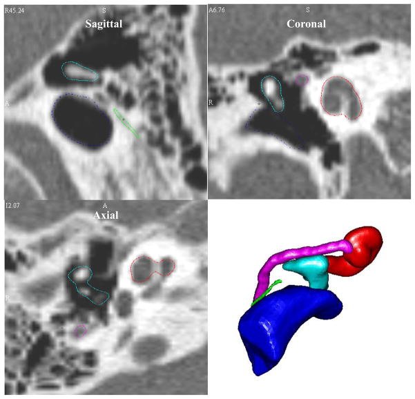
Hypothesis: Using automated methods, vital anatomy of the middle ear can be identified in computed tomographic (CT) scans and used to create 3-dimensional (3D) renderings.
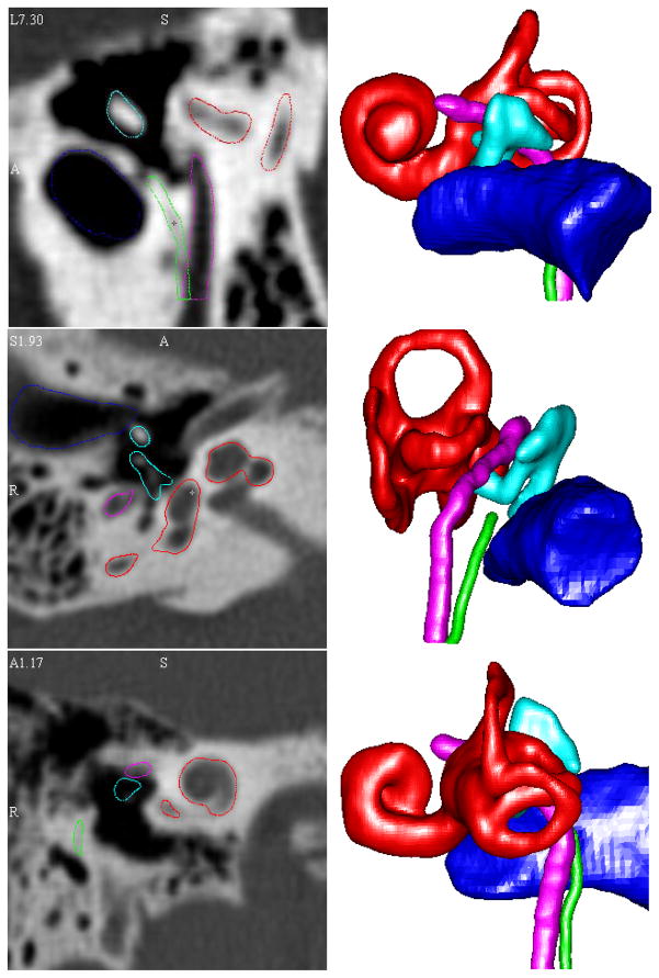
Background: Although difficult to master, clinicians compile 2D data from CT scans to envision 3D anatomy. Computer programs exist that can render 3D surfaces but are limited in that ear structures, for example, the facial nerve, can only be visualized after time-intensive manual identification for each scan. Here, we present results from novel computer algorithms that automatically identify temporal bone anatomy (external auditory canal, ossicles, labyrinth, facial nerve, and chorda tympani).
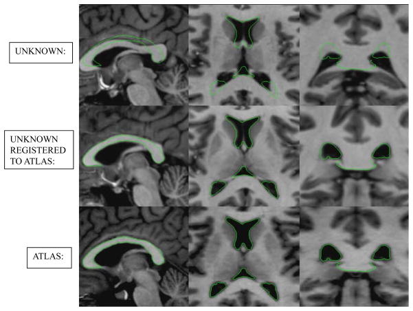
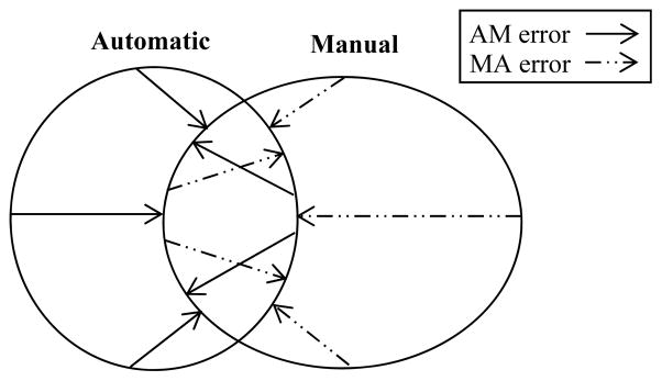
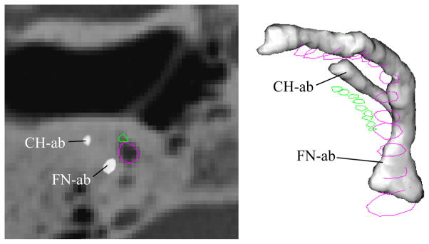
Methods: An atlas of the labyrinth, ossicles, and auditory canal was created by manually identifying the structures in a "normal" temporal bone CT scan. Using well-accepted techniques, these structures were automatically identified in (n = 14) unknown CT images by deforming the atlas to match the unknown volumes. Another automatic localization algorithm was implemented to identify the position of the facial nerve and chorda tympani. Results were compared with manual identification by measuring false-positive and false-negative error.
Results: The labyrinth, ossicles, and auditory canal were identified with mean errors less than 0.5 mm. The mean errors in facial nerve and chorda tympani identification were less than 0.3 mm.
Conclusion: Automated identification of temporal bone anatomy is achievable. The presented combination of techniques was successful in accurately identifying temporal bone anatomy. These results were obtained in less than 10 minutes per patient scan using standard computing equipment.
Figures
References
-
- Jun BC, Song SW, Cho JE, et al. Three-dimensional reconstruction based on images fromspiral high-resolution computed tomography of the temporal bone: anatomy and clinical application. Laryngology & Otology. 2005;119:693–8. - PubMed
-
- Nakashima S, Sando I, Tkahashi H, et al. Computer-aided 3-D reconstruction and measurement of the facial canal and facial nerve. I. Cross-sectional area and diameter: preliminary report. Laryngoscope. 1993;103:1150–6. - PubMed
-
- Takagi A, Sando I, Takahashi H. Computer-aided three-dimensional reconstruction and measurement of semicircular canals and their cristae in man. Acta Otolaryngol. 1989;107:362–5. - PubMed
-
- Green JD, Jr, Marion MS, Erickson BJ, et al. Three-dimensional Reconstruction of the temporal bone. Laryngoscope. 1990;100:1–4. - PubMed
Publication types
MeSH terms
Grants and funding
LinkOut - more resources
Full Text Sources
Other Literature Sources
