. 2008 Nov;1(6):752-61.
doi: 10.1016/j.jcmg.2008.06.007.

Three-dimensional coronary artery microscopy by intracoronary optical frequency domain imaging

Affiliations

Three-dimensional coronary artery microscopy by intracoronary optical frequency domain imaging

Guillermo J Tearney et al. JACC Cardiovasc Imaging. 2008 Nov.

Abstract

Objectives: We present the first clinical experience with intracoronary optical frequency domain imaging (OFDI) in human patients.

Background: Intracoronary optical coherence tomography (OCT) is a catheter-based optical imaging modality that is capable of providing microscopic (approximately 7-microm axial resolution, approximately 30-microm transverse resolution), cross-sectional images of the coronary wall. Although the use of OCT has shown substantial promise for imaging coronary microstructure, blood attenuates the OCT signal, necessitating prolonged, proximal occlusion to screen long arterial segments. OFDI is a second-generation form of OCT that is capable of acquiring images at much higher frame rates. The increased speed of OFDI enables rapid, 3-dimensional imaging of long coronary segments after a brief, nonocclusive saline purge.

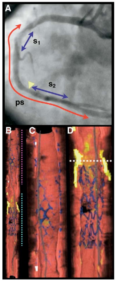
Methods: Volumetric OFDI images were obtained in 3 patients after intracoronary stent deployment. Imaging was performed in the left anterior descending and right coronary arteries with the use of a nonocclusive saline purge rates ranging from 3 to 4 ml/s and for purge durations of 3 to 4 s. After imaging, the OFDI datasets were segmented using previously documented criteria and volume rendered.

Results: Good visualization of the artery wall was obtained in all cases, with clear viewing lengths ranging from 3.0 to 7.0 cm at pullback rates ranging from 5 to 20 mm/s. A diverse range of microscopic features were identified in 2 and 3 dimensions, including thin-capped fibroatheromas, calcium, macrophages, cholesterol crystals, bare stent struts, and stents with neointimal hyperplasia. There were no complications of the OFDI procedure.

Conclusions: Our results demonstrate that OFDI is a viable method for imaging the microstructure of long coronary segments in patients. Given its ability to provide microscopic information in a practical manner, this technology may be useful for studying human coronary pathophysiology in vivo and as a clinical tool for guiding the management of coronary artery disease.


Figures

Figure 1
Figure 1. Patient OFDI-01 Images of Left Anterior Descending Coronary Artery
(A) Right anterior oblique angiogram after stent deployment, showing stent site (s) and 4.2-cm optical frequency domain imaging (OFDI) pullback segment (ps). (B) Maximum intensity projection and (C) cutaway views of 3-dimensional volume-rendered OFDI data set, showing scattered calcium deposits and a large lipid-rich lesion at the distal portion of the pullback segment (red arrowhead). Color scale for B and C: red = artery wall; green = macrophages; yellow = lipid pool; blue = stent; white = calcium; gray = guidewire. Scale bars in B and C, 5.0 mm.
Figure 2
Figure 2. Patient OFDI-01 Longitudinal and Cross-Sectional Images of Left Anterior Descending Artery
(A) Longitudinal optical frequency domain imaging (OFDI) section, corresponding to the cut surface of (Fig. 1C). (B) Expanded view of dotted region in A, demonstrating a large calcific nodule (blue arrowheads) and a lipid pool with a thin fibrous cap (black arrow). (C) Expanded view of an OFDI cross-sectional image obtained at location of the black arrow in B and red arrowhead in Figure 1C, shows a lipid pool with a thin fibrous cap (black arrow) and a dense band of macrophages at the cap–lipid pool interface (green arrow). A thin flap of tissue (black arrowhead) can be seen over the cap. Scale bar in A, 5.0 mm. Scale bar in B, 1.0 mm. Tick marks in C, 0.25 mm. L = lipid pool.
Figure 3
Figure 3. Patient OFDI-02 Images of Right Coronary Artery (Session 2)
(A) Left anterior oblique angiogram after stent deployment, showing previous (s1, BMS) and current (s2, DES) stents and 7.0-cm optical frequency domain imaging (OFDI) pullback segment (ps). (B) Cutaway view of entire 3-dimensional volume rendered OFDI data set (top = proximal; bottom = distal). (C) Expanded view of segment denoted by magenta dotted line in B, showing the BMS. (D) Expanded view of segment denoted by cyan dotted line in B, showing the DES. White dotted line in D is through a lipid-rich lesion, proximal to the DES. Color scale for B to D: red = artery wall; green = macrophages; yellow = lipid pool; blue = stent; white = calcium; gray = guide wire. BMS = bare-metal stent; DES = drug-eluting stent.
Figure 4
Figure 4. Patient OFDI-02 Images of Right Coronary Artery Stents
(A) Fly-through view (distal-proximal) of the BMS shows covered struts underneath the surface of the artery wall, as well as some struts that appear near the luminal surface. (B) Fly-through view (distal-proximal) of the DES demonstrates uncovered struts. (C and D) Optical frequency domain imaging (OFDI) cross-sectional images of the BMS and DES respectively. The OFDI appearance of the struts is different for the 2 stents. Tick marks, 1 mm. Abbreviations as in Figure 3.
Figure 5
Figure 5. Patient OFDI-02 Images of a Distal Right Coronary Artery Thin-Capped Fibroatheroma
(A) Fly-through view (distal-proximal), demonstrates a circumferential lipid-rich lesion with abundant macrophages, partially covered by the stent. (B) An optical frequency domain imaging (OFDI) cross-sectional image obtained at location of white arrowheads in A and dotted line in Figure 3D, shows a circumferential lipid pool (L). Thin cap sites (black arrowheads) can be identified at multiple locations within the cross-sectional image. Macrophages (green arrowheads) and cholesterol crystals (red arrows) can also be seen. Tick marks, 1 mm. *Guide wire artifact.
Figure 6
Figure 6. Patient OFDI-03 Images of Right Coronary Artery
(A) A left anterior oblique angiogram after stent deployment shows stent site (s) and 3.0-cm optical frequency domain imaging (OFDI) pullback segment (ps). (B) Fly-through view (distal-proximal) demonstrates a calcified lesion underneath the stent (arrow). (C) An OFDI cross-sectional image, obtained at location of yellow arrow in B, shows a large calcific nodule from 11- to 4-o'clock. Tick marks, 1 mm.
Figure 7
Figure 7. Patient OFDI-03 Images of Right Coronary Artery Stent
(A) Perspective cutaway view of entire 3-dimensional volume rendered optical frequency domain imaging (OFDI) data set (left = proximal; right = distal), demonstrating the stent (blue), a side branch (yellow arrow), and a large calcific nodule (red arrowhead). (B) Longitudinal section through a portion of the dataset, corresponding to the gray dotted rectangle in A. The side branch (black arrow) and calcific nodule (red arrowhead) are evident. Scale bar in B, 1.0 mm.

Comment in

References

    1. Huang D, Swanson EA, Lin CP, et al. Optical coherence tomography. Science. 1991;254:1178–81. - PMC - PubMed
    1. Brezinski ME, Tearney GJ, Bouma BE, et al. Imaging of coronary artery microstructure (in vitro) with optical coherence tomography. Am J Cardiol. 1996;77:92–3. - PubMed
    1. Tearney GJ, Brezinski ME, Boppart SA, et al. Images in cardiovascular medicine. Catheter-based optical imaging of a human coronary artery Circulation. 1996;94:3013. - PubMed
    1. Tearney GJ, Jang IK, Kang DH, et al. Porcine coronary imaging in vivo by optical coherence tomography. Acta Cardiol. 2000;55:233–7. - PubMed
    1. Jang IK, Tearney G, Bouma B. Visualization of tissue prolapse between coronary stent struts by optical coherence tomography: comparison with intravascular ultrasound. Circulation. 2001;104:2754. - PubMed

Publication types

MeSH terms