Flexible electrical recording from cells using nanowire transistor arrays
- PMID: 19365078
- PMCID: PMC2678623
- DOI: 10.1073/pnas.0902752106
Flexible electrical recording from cells using nanowire transistor arrays
Abstract
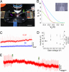
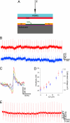
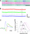
Semiconductor nanowires (NWs) have unique electronic properties and sizes comparable with biological structures involved in cellular communication, thus making them promising nanostructures for establishing active interfaces with biological systems. We report a flexible approach to interface NW field-effect transistors (NWFETs) with cells and demonstrate this for silicon NWFET arrays coupled to embryonic chicken cardiomyocytes. Cardiomyocyte cells were cultured on thin, optically transparent polydimethylsiloxane (PDMS) sheets and then brought into contact with Si-NWFET arrays fabricated on standard substrates. NWFET conductance signals recorded from cardiomyocytes exhibited excellent signal-to-noise ratios with values routinely >5 and signal amplitudes that were tuned by varying device sensitivity through changes in water gate-voltage potential, V(g). Signals recorded from cardiomyocytes for V(g) from -0.5 to +0.1 V exhibited amplitude variations from 31 to 7 nS whereas the calibrated voltage remained constant, indicating a robust NWFET/cell interface. In addition, signals recorded as a function of increasing/decreasing displacement of the PDMS/cell support to the device chip showed a reversible >2x increase in signal amplitude (calibrated voltage) from 31 nS (1.0 mV) to 72 nS (2.3 mV). Studies with the displacement close to but below the point of cell disruption yielded calibrated signal amplitudes as large as 10.5 +/- 0.2 mV. Last, multiplexed recording of signals from NWFET arrays interfaced to cardiomyocyte monolayers enabled temporal shifts and signal propagation to be determined with good spatial and temporal resolution. Our modular approach simplifies the process of interfacing cardiomyocytes and other cells to high-performance Si-NWFETs, thus increasing the experimental versatility of NWFET arrays and enabling device registration at the subcellular level.
Conflict of interest statement
The authors declare no conflict of interest.
Figures


Similar articles
-
Synthetic nanoelectronic probes for biological cells and tissues.Annu Rev Anal Chem (Palo Alto Calif). 2013;6:31-51. doi: 10.1146/annurev-anchem-062012-092623. Epub 2013 Feb 28. Annu Rev Anal Chem (Palo Alto Calif). 2013. PMID: 23451719 Free PMC article. Review.
-
Nanowire transistor arrays for mapping neural circuits in acute brain slices.Proc Natl Acad Sci U S A. 2010 Feb 2;107(5):1882-7. doi: 10.1073/pnas.0914737107. Epub 2010 Jan 19. Proc Natl Acad Sci U S A. 2010. PMID: 20133836 Free PMC article.
-
Electrical recording from hearts with flexible nanowire device arrays.Nano Lett. 2009 Feb;9(2):914-8. doi: 10.1021/nl900096z. Nano Lett. 2009. PMID: 19170614 Free PMC article.
-
Graphene and nanowire transistors for cellular interfaces and electrical recording.Nano Lett. 2010 Mar 10;10(3):1098-102. doi: 10.1021/nl1002608. Nano Lett. 2010. PMID: 20136098 Free PMC article.
-
Functionalized Organic Thin Film Transistors for Biosensing.Acc Chem Res. 2019 Feb 19;52(2):277-287. doi: 10.1021/acs.accounts.8b00448. Epub 2019 Jan 8. Acc Chem Res. 2019. PMID: 30620566 Review.
Cited by
-
Multi-electrode array technologies for neuroscience and cardiology.Nat Nanotechnol. 2013 Feb;8(2):83-94. doi: 10.1038/nnano.2012.265. Nat Nanotechnol. 2013. PMID: 23380931 Review.
-
Nanowire active-matrix circuitry for low-voltage macroscale artificial skin.Nat Mater. 2010 Oct;9(10):821-6. doi: 10.1038/nmat2835. Epub 2010 Sep 12. Nat Mater. 2010. PMID: 20835235
-
Wireless in vivo Recording of Cortical Activity by an Ion-Sensitive Field Effect Transistor.Sens Actuators B Chem. 2023 May 1;382:133549. doi: 10.1016/j.snb.2023.133549. Epub 2023 Feb 21. Sens Actuators B Chem. 2023. PMID: 36970106 Free PMC article.
-
Synthetic nanoelectronic probes for biological cells and tissues.Annu Rev Anal Chem (Palo Alto Calif). 2013;6:31-51. doi: 10.1146/annurev-anchem-062012-092623. Epub 2013 Feb 28. Annu Rev Anal Chem (Palo Alto Calif). 2013. PMID: 23451719 Free PMC article. Review.
-
Back to the future.Nat Nanotechnol. 2011 Oct 7;6(10):607-8. doi: 10.1038/nnano.2011.179. Nat Nanotechnol. 2011. PMID: 21979229 No abstract available.
References
-
- Hille B. Ion Channels of Excitable Membranes. Sunderland, MA: Sinauer; 2001.
-
- Zipes DP, Jalife J. Cardiac Electrophysiology : From Cell to Bedside. Philadelphia: Saunders; 2004.
-
- Dhein S, Mohr FW, Delmar M. Practical Methods in Cardiovascular Research. Berlin: Springer; 2005.
-
- Fast VG, Kleber AG. Aniosotropic conduction in monolayers of neonatal rat-heart cells cultured on collagen. Circ Res. 1994;75:591–595. - PubMed
-
- Kleber AG, Rudy Y. Basic mechanisms of cardiac impulse propagation and associated arrhythmias. Physiol Rev. 2004;84:431–488. - PubMed
Publication types
MeSH terms
Substances
Grants and funding
LinkOut - more resources
Full Text Sources
Other Literature Sources
Miscellaneous

