

doi: 10.1364/oe.17.006068.
Microfluidic cell counter with embedded optical fibers fabricated by femtosecond laser ablation and anodic bonding
Affiliations
- PMID: 19365429
- PMCID: PMC3155247
- DOI: 10.1364/oe.17.006068
Item in Clipboard
Microfluidic cell counter with embedded optical fibers fabricated by femtosecond laser ablation and anodic bonding
Opt Express.
.
Abstract
A simple fabrication technique to create all silicon/glass microfluidic devices is demonstrated using femtosecond laser ablation and anodic bonding. In a first application, we constructed a cell counting device based on small angle light scattering. The counter featured embedded optical fibers for multiangle excitation and detection of scattered light and/or fluorescence. The performance of the microfluidic cell counter was benchmarked against a commercial fluorescence-activated cell sorter.
Figures

Fiber placement in a femtosecond laser ablated groove.
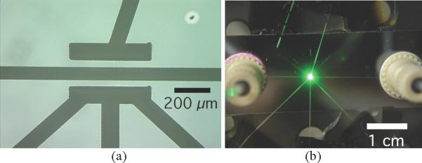
(a) White light image of the fluid channel (horizontal) with four fiber grooves: one above at 14 degrees from normal and three below at −45, 0, and 45 degrees from normal. (b) Nanoport connectors were attached to either end of the fluid channel. In these experiments, light was delivered through the fiber at 0 degrees from normal and collected through the fiber opposite it at 14 degrees from normal.
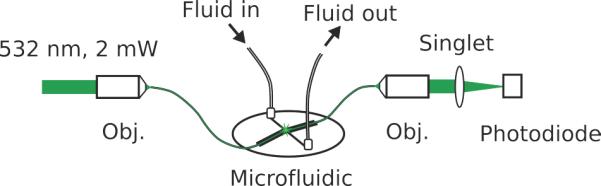
An illustration of the experimental setup.
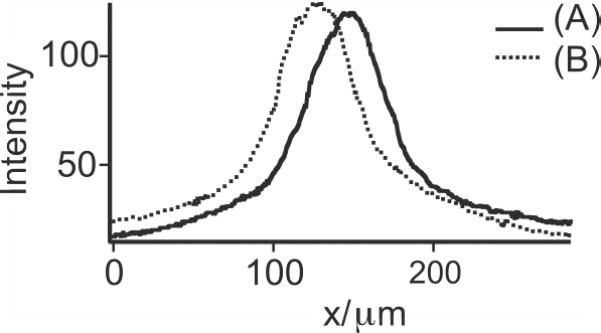
Overlap of the illumination region with the anticipated detection region was determined by filling the fluid channel with a fluorescent dye and then imaging the fluorescence. Lineouts along the center of the fluid channel (parallel to the x axis) show the overlap of the illumination region (A) with the detection region (B).
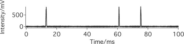
Sample data set showing the peaks from light scattered by passing HeLa cells.
References
-
- Altendorf E, Zebert D, Holl M, Yager P. Differential blood cell counts obtained using a microchannel based flow cytometer. IEEE International Conference on Solid-State Sensors and Actuators; IEEE; 1997. pp. 531–534.
-
- Brown M, Wittwer C. Flow cytometry: principles and clinical applications in hematology. Clin. Chem. 2000;46:1221–1229. - PubMed
-
- Pamme N, Koyama R, Manz A. Counting and sizing of particles and particle agglomerates in a microfluidic device using laser light scattering: application to a particle-enhanced immunoassay. Lab Chip. 2003;3:187–192. - PubMed
-
- Chen H, Wang Y. Optical microflow cytometer for particle counting, sizing and fluorescence detection. Microfluid. Nanofluid. 2008 DOI 10.1007/s10404-008-0335-z.
-
- Chabinyc ML, Chiu DT, Cooper McDonald J, Stroock AD, Christian JF, Karger AM, Whitesides GM. An integrated fluorescence detection system in poly(dimethylsiloxane) for microfluidic applications. Anal. Chem. 2001;73:4491–4498. - PubMed
Publication types
MeSH terms
Grants and funding
LinkOut - more resources
Full Text Sources
Other Literature Sources
