. 2009 Jun 12;284(24):16452-16462.
doi: 10.1074/jbc.M808262200. Epub 2009 Apr 16.

Dynamic partnership between KCNQ1 and KCNE1 and influence on cardiac IKs current amplitude by KCNE2

Affiliations

Dynamic partnership between KCNQ1 and KCNE1 and influence on cardiac IKs current amplitude by KCNE2

Min Jiang et al. J Biol Chem. .

Abstract

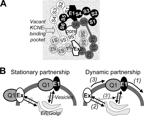
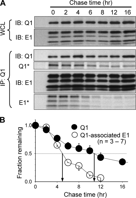
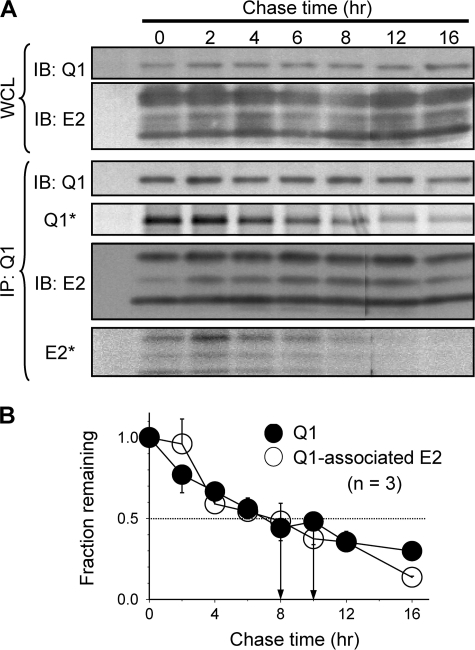
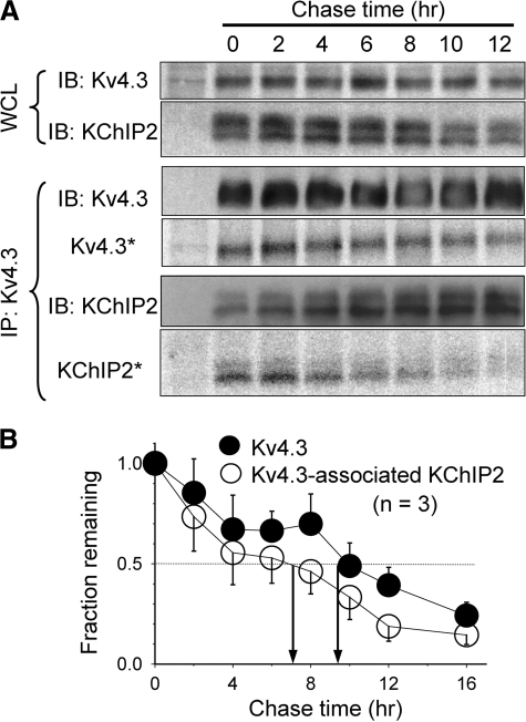
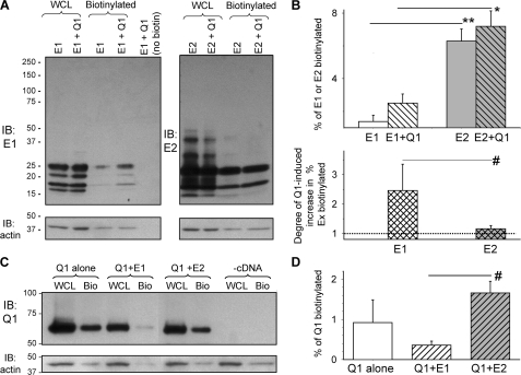
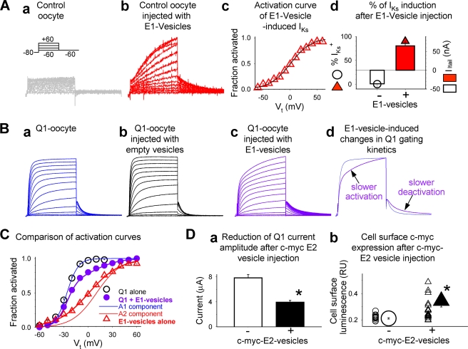
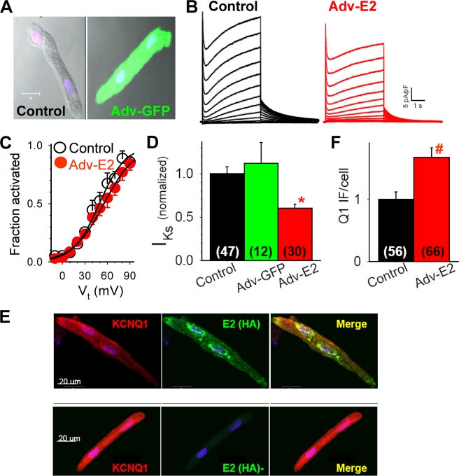
Cardiac slow delayed rectifier (IKs) channel is composed of KCNQ1 (pore-forming) and KCNE1 (auxiliary) subunits. Although KCNE1 is an obligate IKs component that confers the uniquely slow gating kinetics, KCNE2 is also expressed in human heart. In vitro experiments suggest that KCNE2 can associate with the KCNQ1-KCNE1 complex to suppress the current amplitude without altering the slow gating kinetics. Our goal here is to test the role of KCNE2 in cardiac IKs channel function. Pulse-chase experiments in COS-7 cells show that there is a KCNE1 turnover in the KCNQ1-KCNE1 complex, supporting the possibility that KCNE1 in the IKs channel complex can be substituted by KCNE2 when the latter is available. Biotinylation experiments in COS-7 cells show that although KCNE1 relies on KCNQ1 coassembly for more efficient cell surface expression, KCNE2 can independently traffic to the cell surface, thus becoming available for substituting KCNE1 in the IKs channel complex. Injecting vesicles carrying KCNE1 or KCNE2 into KCNQ1-expressing oocytes leads to KCNQ1 modulation in the same manner as KCNQ1+KCNEx (where x=1 or 2) cRNA coinjection. Thus, free KCNEx peptides delivered to the cell membrane can associate with existing KCNQ1 channels to modulate their function. Finally, adenovirus-mediated KCNE2 expression in adult guinea pig ventricular myocytes exhibited colocalization with native KCNQ1 protein and reduces the native IKs current density. We propose that in cardiac myocytes the IKs current amplitude is under dynamic control by the availability of KCNE2 subunits in the cell membrane.


Figures

FIGURE 1.
FIGURE 1.
A, schematic arrangement of transmembrane helices in a KCNQ1-KCNE channel complex. The view is from the extracellular perspective. The arrangement of transmembrane helices in the Q1 channel is based on the Kv channel crystal structures (Protein Data Bank codes 2A79 and 2R9R) (26, 27). The four Q1 subunits are arranged around a central pore and are color-coded as white, light gray, dark gray, and black. The voltage-sensing domain (S1–S4) of each Q1 subunit is juxtaposed to the pore domains (S5 and S6) of the adjacent Q1 subunit. Experimental data suggest that the E1 transmembrane domain resides in a KCNE-binding pocket between voltage-sensing domains of two adjacent Q1 subunits (12, 28), where E1 simultaneously interacts with S1 (12) and S4 (11) of two adjacent Q1 voltage-sensing domains and with S6 of a third Q1 subunit (5, 7, 8, 29). Furthermore, optimally two KCNE subunits simultaneously bind to a Q1 channel (4, 25), likely in diagonal positions as depicted here. In the cardiac IKs channel, E1 is an obligate component (occupying one KCNE-binding pocket), whereas E1 or another KCNE subunit (Ex) occupies the other KCNE-binding pocket. B, two possible scenarios of Q1-KCNE association. Left panel, stationary partnership where Q1 and KCNE subunits form stable complexes without dissociation or exchange of the KCNE components during transits among ER, Golgi apparatus, cytosolic vesicles, and the cell surface membrane. Right panel, dynamic partnership where E1 can dissociate from the Q1 channel (process (1)) and the vacancy is filled by another KCNE subunit, Ex, which can take place in the cell surface membrane (process (3)) after Ex traffics to the cell surface independent of Q1 (process (2)) or during transits among cytosolic vesicular compartments (process 3′).
FIGURE 2.
FIGURE 2.
Pulse-chase experiments to test the turnover rates of KCNQ1 and KCNQ1-associated KCNE1. A, immunoblot and autoradiograph images from a representative experiment. COS-7 cells expressing Q1 and E1 were metabolically labeled with [35S]Met for 1 h and chased with unlabeled Met for up to 16 h (chase times marked at the top). WCLs were subjected to Q1 and E1 coimmunoprecipitation with V5 mAb targeting the V5 epitope engineered into the C terminus of Q1 and Q1-associated E1. Upper two rows, monitoring total Q1 and E1 protein levels in WCLs. Lower four rows, monitoring protein levels (IB: Q1 and IB: E1) and radioactivity levels (Q1* and E1*) of Q1 and Q1-associated E1 in the immunoprecipitates (IP: Q1). These data are from the same gel: immunoprecipitates were fractionated by SDS-PAGE, and part of the proteins was blotted to polyvinylidene difluoride membrane for immunoblot (IB) measurement, and the remaining proteins in the gel were used for radioactivity measurement. B, data summary. Autoradiograph band intensities at different chase times were normalized to the value at time zero (fraction remaining) and plotted against chase times. The multiple E1 bands represented differentially glycosylated forms (12), and band intensities were combined for quantification. Shown are the means ± S.E. from three to seven experiments. Arrows point to the estimated half-time (T½) of turnover for Q1 and Q1-associated E1 (11 and 5 h, respectively).
FIGURE 3.
FIGURE 3.
Pulse-chase experiments to test the turnover rates of KCNQ1 and KCNQ1-associated KCNE2. The experimental procedures and format of data presentation are the same as those described for Fig. 2. The multiple E2 bands represented differentially glycosylated forms (21), and band intensities were combined for quantification. The data in B were summarized from three experiments. The estimated T½ values of turnover of Q1 and Q1-associated E2 are 10 and 8 h, respectively. IB, immunoblot.
FIGURE 4.
FIGURE 4.
Pulse-chase experiments to test the turnover rates of Kv4. 3 and Kv4.3-associated KChIP2. The experimental procedures and format of data presentation are the same as those described for Fig. 2. KChIP2 migrates as two closely spaced bands. Both bands were included in quantification. The data in B were summarized from three experiments. The estimated T½ values of turnover of Kv4.3 and Kv4.3-associated KChIP2 are 9 and 7 h, respectively. IB, immunoblot.
FIGURE 5.
FIGURE 5.
Biotinylation experiments to test cell surface KCNE1, KCNE2, and KCNQ1 expression. A and B, cell surface E1 and E2 expression and influence of Q1 coassembly. Surface proteins bearing exposed lysine residues in COS-7 cells were labeled with an amine-reactive biotin derivative on ice for 30 min. After cell lysis, 10% of the WCLs were reserved for direct immunoblotting, and the remaining WCLs were incubated with NeutrAvidin-conjugated agarose beads to retrieve biotinylated proteins. WCL, biotinylated (cell surface) fraction, and transfected cDNA(s) are marked at the top. A, immunoblot images from a representative experiment. Upper panels, E1 (left panel) and E2 (right panel) immunoblots. Lower panels, actin immunoblots from the same membranes after stripping. The rightmost lane in the left panel is NeutrAvidin-retrieved fraction from whole cell lysates without biotin label (control for NeutrAvidin specificity). Band intensities were determined by densitometry and background-subtracted. The multiple (differentially glycosylated) E1 or E2 bands were combined for quantification. The percentage of cell surface fraction was calculated as: % biotinylated = 100*[biotinylated/(biotinylated + WCL*10)], where biotinylated and WCL denote immunoblot band intensities in these two fractions. The band intensity values for WCL needed to be multiplied by 10 because only 10% of WCL was used for direct immunoblotting. B, data summary. Upper panel, percentage of total E1 or E2 that was biotinylated, expressed alone or coexpressed with Q1. Lower panel, increase in biotinylated E1 or E2 by Q1 coexpression, expressed as ratio of the percentage biotinylated Ex in “Ex+Q1” versus “Ex alone”. C and D, cell surface Q1 expression and influence of E1 or E2 coassembly. C, representative immunoblot images. Upper panel, Q1 immunoblots of WCL and biotinylated fraction (Bio). Lower panel, actin immunoblot images from the same gels. The cDNAs used for transfection are listed on top; -cDNA represents untransfected control COS-7 cells. D, percentage of total Q1 that was biotinylated when expressed alone or coexpressed with E1 or E2. The data in B and D were pooled from three to six experiments. **, p < 0.001; *, p < 0.01; #, p < 0.05.
FIGURE 6.
FIGURE 6.
Oocyte vesicle injection experiments to test whether KCNE peptides delivered to the cell membranes can modulate KCNQ1 channel function. The vesicles were prepared from COS-7 cells transfected with cDNA encoding E1 or c-Myc-E2 (c-Myc epitope engineered into E2 extracellular domain (34)) or without transfection (E1, c-Myc E2, and empty vesicles, respectively). The vesicles were injected into control oocytes (without cRNA injection) or Q1-oocytes (oocytes injected with Q1 cRNA, 10 ng/oocyte, 24 h before vesicle injection). All current traces were elicited by the voltage clamp protocol diagrammed in panel a of A: from a holding voltage of −80 mV, 2-s pulses to test voltage (Vt) ranging from −60 to +60 mV in 10-mV increments are applied once every 15 s. The test pulses were followed by a repolarizing step to −60 mV to monitor tail current amplitudes. A, testing the effects of injecting E1 vesicles into control oocytes. Panel a, representative current traces recorded from a control oocyte. Panel b, IKs current detected in a control oocyte ∼10 h after E1 vesicle injection. Panel c, average isochronal (2 s) activation curve of IKs current recorded from control oocytes injected with E1 vesicles. Peak amplitudes of tail currents were normalized by the estimated maximal tail current amplitude (fraction activated) and plotted against Vt. The data were fit with a single Boltzmann function: fraction activated = 1/[1 + exp ((V0.5Vt)/k)], where V0.5 (1.0 ± 2.2 mV) and k (19.1 ± 0.6 mV) are half-maximal activation voltage and slope factor (n = 11). Panel d, percentage of E1 vesicle injected oocytes that manifested IKs (% IKs+, symbols, left coordinate) and the mean IKs current amplitude in these oocytes (measured from peak amplitude of tail currents after Vt +60 mV, histogram bars, right coordinate). The data were collected from 14 oocytes without E1 vesicle injection, and from 22 oocytes 8–22 h after E1 vesicle injection. B, testing the effects of injecting E1 or empty vesicles into Q1-oocytes. Panel a, current traces from a Q1-oocyte without vesicle injection. Panel b, current traces from a Q1-oocyte ∼20 h after empty vesicle injection. Panel c, current traces from a Q1-oocyte ∼10 h after E1 vesicle injection. Panel d, superimposed current traces from two Q1-oocytes, one without (blue) and the other with (purple) E1 vesicle injection. The arrows point to the slow activation and deactivation phases induced by E1 vesicles. C, average isochronal activation curves from three groups of oocytes: 1) Q1-oocytes without vesicle injection (Q1 alone, black open circles), 2) Q1-oocytes injected with E1 vesicles (purple closed circles), and 3) control oocytes injected with E1 vesicles (E1 vesicles alone, same data as in panel c of A). Group 1 data were fit with a single Boltzmann function as described above (V0.5 = −27.0 ± 0.6 mV, k = 7.6 ± 0.2 mV, n = 5). Group 2 data were fit with a double Boltzmann function: fraction activated = A1/[1 + exp ((V1Vt)/k1)] + A2/[1 + exp ((V2Vt)/k2)], where A1 (0.70 ± 0.04) and A2 (0.30 ± 0.04) represent the fractions of current activated in the negative and positive voltage ranges, V1 (−26.0 ± 0.6 mV), k1 (6.9 ± 0.3 mV), V2 (10.4 ± 3.8 mV), and k2 (14.9 ± 0.7 mV) are the half-maximum voltages and slope factors of the two components (n = 13). The thin curves are activation curves calculated for the A1 (blue) and A2 (red) components. D, injecting c-Myc E2 vesicles led to a decrease in Q1 current amplitude and oocyte cell surface expression of c-Myc epitope. Panel a, mean current amplitudes measured as time-dependent currents during a 2-s step to +40 mV in Q1-oocytes injected with empty or c-Myc E2 vesicles (open and closed histogram bars, respectively). Panel b, magnitudes of cell surface luminescence in Q1-oocytes without or with c-Myc E2 vesicle injection (3–22 h after vesicle injection). The data from individual oocytes are shown as small symbols, and the mean data are shown as large symbols. *, p < 0.01.
FIGURE 7.
FIGURE 7.
Adenovirus-mediated KCNE2 expression in adult guinea pig ventricular myocytes to test whether KCNE2 can associate with native KCNQ1-KCNE1 to modulate IKs current density. Adult (2–3 months old) guinea pig ventricular myocytes were maintained in serum-free medium for 4 days. The myocytes were infected with adenoviruses harboring eGPF gene (Adv-GFP) or KCNE2 (Adv-E2, with an HA tag engineered into the C terminus) (35) at ∼ 2 × 10¹⁰ particles/ml for 2 h. Whole cell currents were recorded on days 3 and 4. A, top panel, superimposed differential interference contrast and fluorescence images of two myocytes, the one on the right infected with Adv-GFP and the one on the left as time control. B, Adv-E2 infection reduced IKs without altering gating kinetics. C, Adv-E2 infection did not change the voltage dependence of IKs activation. D, IKs current density in time control, Adv-GFP, and Adv-E2 infected guinea pig ventricular myocytes (normalized by the mean value in control myocytes). E, confocal images of immunofluorescence from two cultured guinea pig ventricular myocytes, stained for Q1 (Q1 goat Ab/Alexa568 anti-goat, left panel), and HA tag of E2 (HA mouse Ab/Alexa488 anti-mouse, middle panel). Right panel, merge of Alexa568 and Alexa488 signals. F, pixel contents of Q1 immunofluorescence (Q1 IF) per cell in control and Adv-E2-infected myocytes (normalized to the mean value from control myocytes). In D and F, the numbers of cells studied are listed in parentheses. *, p < 0.01.

Similar articles

Cited by

References

    1. Jost M., Virág L., Bitay M., Takács J., Lengyel C., Biliczki P., Nagy Z., Bogáts G., Lathrop D. A., Papp J. G., Varró A. ( 2005) Circulation 112, 1392– 1399 - PubMed
    1. Barhanin J., Lesage F., Guillemare E., Fink M., Lazdunski M., Romey G. ( 1996) Nature 384, 78– 80 - PubMed
    1. Sanguinetti M. C., Curran M. E., Zou A., Shen J., Spector P. S., Atkinson D. L., Keating M. T. ( 1996) Nature 384, 80– 83 - PubMed
    1. Chen H., Kim L. A., Rajan S., Xu S., Goldstein S. A. N. ( 2003) Neuron 40, 15– 23 - PubMed
    1. Tapper A. R., George A. L., Jr. ( 2001) J. Biol. Chem. 276, 38249– 38254 - PubMed

Publication types

MeSH terms

LinkOut - more resources