. 2008:6913:69134U1-69134U8.
doi: 10.1117/12.772781.

C-arm based cone-beam CT using a two-concentric-arc source trajectory: system evaluation

Affiliations

C-arm based cone-beam CT using a two-concentric-arc source trajectory: system evaluation

Joseph Zambelli et al. Proc SPIE Int Soc Opt Eng. 2008.

Abstract

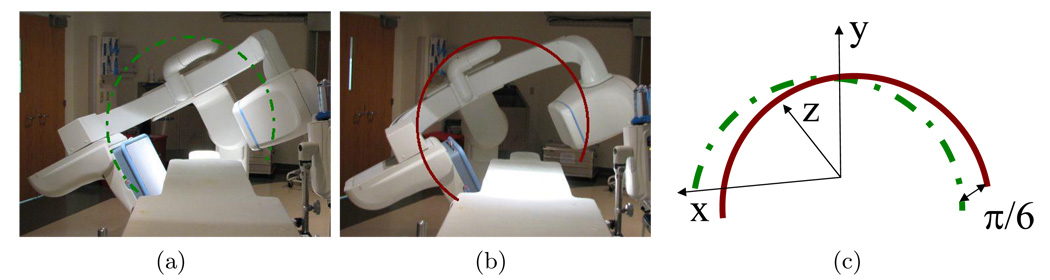
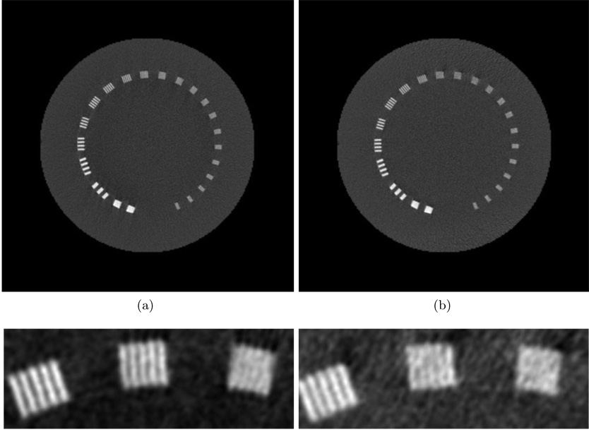
The current x-ray source trajectory for C-arm based cone-beam CT is a single arc. Reconstruction from data acquired with this trajectory yields cone-beam artifacts for regions other than the central slice. In this work we present the preliminary evaluation of reconstruction from a source trajectory of two concentric arcs using a flat-panel detector equipped C-arm gantry (GE Healthcare Innova 4100 system, Waukesha, Wisconsin). The reconstruction method employed is a summation of FDK-type reconstructions from the two individual arcs. For the angle between arcs studied here, 30°, this method offers a significant reduction in the visibility of cone-beam artifacts, with the additional advantages of simplicity and ease of implementation due to the fact that it is a direct extension of the reconstruction method currently implemented on commercial systems. Reconstructed images from data acquired from the two arc trajectory are compared to those reconstructed from a single arc trajectory and evaluated in terms of spatial resolution, low contrast resolution, noise, and artifact level.


Figures

Figure 1
Figure 1
The positioning arm parked at 15° (a), where the gantry spins along the path denoted by the solid arc. The positioning arm parked at −15° (b), where the gantry spins along the path denoted by the dashed arc. The complete source trajectory generated by these two motions of the C-arm gantry (c).
Figure 2
Figure 2
Reconstructed images of the yz plane at x=−0.39 mm for the Defrise phantom using a conventional FDK reconstruction (a), and a combined FDK reconstruction (b).
Figure 3
Figure 3
Reconstructed images of the modified Rando phantom: (a) and (d) are xz slices at y=23.05 mm using conventional and combined FDK reconstruction, respectively; (b) and (e) are yz slices at x=20.70 mm using a conventional and combined FDK reconstruction, respectively. Note the improvement in image quality for the combined FDK reconstruction in the regions indicated by the arrows. Enlargements of the lower left corner of the yz slice presented in (b) and (e) are displayed in (c) and (f).
Figure 4
Figure 4
Reconstructed images of the Catphan CTP528 high resolution module are shown in (a) for conventional FDK reconstruction and (b) for the combined FDK reconstruction. Zoomed reconstructions of the 8 to 10 lp/cm section of the Catphan CTP528 high resolution module are shown in (c) for conventional FDK reconstruction and (d) for the combined FDK reconstruction.
Figure 5
Figure 5
Measured MTF for the two reconstruction methods. The dashed blue line is the conventional FDK reconstruction MTF and the solid green line is the combined FDK reconstruction MTF.
Figure 6
Figure 6
Reconstructed images of the CTP515 low contrast module. (a) and (b) show results for 70 kVp scans with conventional FDK and combined FDK reconstruction, respectively. (e) and (f) show results for 70 kVp scans with conventional FDK and combined FDK reconstruction, respectively, with scatter correction included. (c) and (d) show results for 95 kVp scans with conventional FDK and combined FDK reconstruction, respectively. (g) and (h) show results for 95 kVp scans with conventional FDK and combined FDK reconstruction, respectively, with scatter correction included.
Figure 7
Figure 7
Comparison of dose measurements for a 70 kVp scan. Measurements from a single arc scan (blue) and the summed contributions from the two scan (red) are shown in (a). The individual contributions from the 70 kVp two arc scan, as well as central and average doses, are shown in (b).
Figure 8
Figure 8
Reconstructed xz slice at y=4.9 mm of a porcine model using conventional FDK reconstruction (a), and combined FDK reconstruction (b).

References

    1. Jaffray DA, Siewerdsen JH. Cone-beam computed tomography with a flat-panel imager: initial performance characterization. Med. Phys. 27;2000:1311–1320. - PubMed
    1. Chen B, Ning R. Cone-beam volume CT breast imaging: Feasibility study. Med. Phys. 2002;29:755–770. - PubMed
    1. Boone JM, Nelson TR, Lindfors KK, Seibert JA. Dedicated breast CT: radiation dose and image quality evaluation. Radiology. 2001;221:657–667. - PubMed
    1. Siewerdsen JH, Moseley DJ, Burch S, Bisland SK, Bogaards A, Wilson BC, Jaffray DA. Volume CT with a flat-panel detector on a mobile, isocentric C-arm: pre-clinical investigation in guidance of minimally invasive surgery. Med Phys. 2005 Jan;32:241–254. - PubMed
    1. Fahrig R, Fox AJ, Lownie S, Holdsworth DW. Use of a C-arm system to generate true three-dimensional computed rotational angiograms: preliminary in vitro and in vivo results. AJNR Am J Neuroradiol. 1997 Sep;18:1507–1514. - PMC - PubMed

LinkOut - more resources