

Review
doi: 10.1039/b808893d.
Epub 2008 Sep 5.
Droplet interface bilayers
Affiliations
- PMID: 19396383
- PMCID: PMC2763081
- DOI: 10.1039/b808893d
Item in Clipboard
Review
Droplet interface bilayers
Mol Biosyst.
2008 Dec.
Abstract
Droplet interface bilayers (DIBs) provide a superior platform for the biophysical analysis of membrane proteins. The versatile DIBs can also form networks, with features that include built-in batteries and sensors.
Figures

Origins of droplet interface bilayers. (a) Notes made soon after the meeting in 2005 showing possibilities including droplet networks. “Not much to it really, GMO/squalene and just make the micro or milli droplets, touch together and see if there’s a bilayer”, David Needham. (b) Device made by Tsofina and colleagues, and published in 1966, in which a bilayer is formed between two aqueous compartments in heptane containing phospholipids. Reprinted by permission from Macmillan Publishers Ltd: Nature 1966, 212, 681–683, copyright 1966.

Methods of bilayer formation: old versus new. (a) Montal-Mueller (MM) bilayers are created by folding the leaflets of two air/water lipid monolayers across an aperture ~100 μm in diameter in a Teflon film (typically 25-μm thick). This process takes minutes to learn but months to master. (b) By contrast, monolayers surrounding two droplets spontaneously snap together when brought into proximity. (c) By hanging the droplets on movable electrodes, droplet interface bilayers (DIB) can be made and pulled apart repeatedly. Conveniently, precise movement of one droplet with a micromanipulator also allows modulation of the bilayer area while the droplets are joined. These droplets are about 700 μm in diameter.

Lipid-out and lipid-in DIB formation. (a) Lipid-out DIB formation. Aqueous droplets are pipetted onto agarose-coated Ag/AgCl electrodes and submerged in an oil-lipid solution. After a stabilization period to allow the droplets to become encased by monolayers, they are brought into contact and form a bilayer. (b) Lipid-in DIB formation. Two types of aqueous droplet, containing lipid vesicles of different compositions, are formed by injection into an oil reservoir. Vesicles fuse with the oil-water interface of each droplet and form monolayers. The droplets are then brought together to form an asymmetric bilayer. Adapted with permission from J. Am. Chem. Soc. 2008, 130, 5878–5879. Copyright 2008 Am. Chem. Soc.

A DHB system for simultaneous TIRF microscopy and electrical recording. (a) Diagram of DHB including electrodes and TIRF illumination. As the underlying substrate can be relatively large, it is easy to accommodate an electrode far from the bilayer, thereby simplifying the incorporation of electrical recording into a system for simultaneous imaging. (b) Image of a DHB on an inverted microscope showing the bilayer contact area. Adapted with permission from J. Am. Chem. Soc. 2007, 129, 16042–16047. Copyright 2007 Am. Chem. Soc.
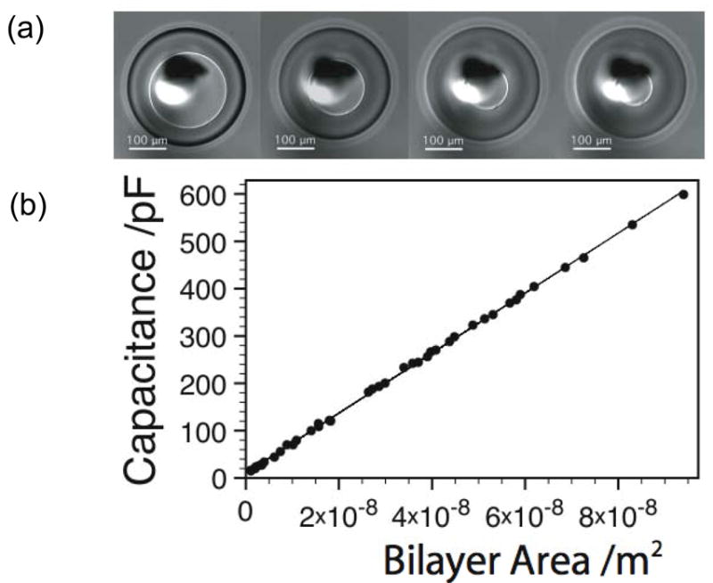
Measurement of specific capacitance by modulating the bilayer area of a DHB. (a) Image of a DHB showing control of the bilayer area. (b) Measured capacitance values for a DPhPC bilayer in hexadecane as a function of bilayer area.
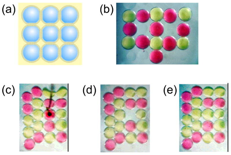
Creating and manipulating bilayer networks. (a) By using a dimpled surface as a miniature “egg-crate”, patterns of connected droplets are easily formed. (b) Light microscope image of a DIB assembly. The pink and yellow droplets are filled with dyes for visualization. The droplets are about 700 μm in diameter. Each interface between droplets is a lipid bilayer. (c) This bright-field image of twenty dye-filled droplets shows two types of ordering. The five droplets along the left edge are outside the dimple array and pack in the compact hexagonal fashion. The remaining fifteen droplets settle into the dimples and are arranged in a square lattice. The black object is an agarose-tipped electrode that has punctured a pink droplet. The hydrophilic gel acts as an anchor, and when the electrode is lifted, the droplet is excised from the network. (d) The adjacent bilayers remain intact, despite the cleavage of four bilayers as the droplet is extracted. (e) A stabilized yellow droplet is rolled into the empty dimple, demonstrating the ready reorganization of a network. This process can be repeated as often as needed. Adapted with permission from J. Am. Chem. Soc. 2007, 129, 8650–8655. Copyright 2007 Am. Chem. Soc.

The behavior of OmpG in symmetric and asymmetric bilayers. (a) Current traces showing OmpG gating: Top: neutral DIB (0/0), Middle: insertion from the negative side of an asymmetric DIB (−/+), and Bottom: insertion from the positive side of an asymmetric DIB (+/−). A potential of +50 mV was applied. The buffer used was 10 mM HEPES, 200 mM KCl, pH 7.0. Protein was in the grounded droplets. (b) Comparison of mean gating probabilities (Pgating) of OmpG in a symmetric neutral planar bilayer (0/0*), symmetric neutral lipid-in DIB (0/0), and asymmetric DIBs (−/+ and +/−). Pgating is defined as the ratio of the time a pore resides in partially or fully closed states to the total recording time. Error bars represent one standard error and are based on at least ten pores. Reprinted with permission from J. Am. Chem. Soc. 2008, 130, 5878–5879. Copyright 2008 Am. Chem. Soc.
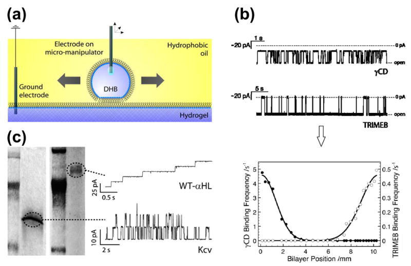
Scanning gels with DHBs. (a) Schematic showing a droplet, which forms a DHB that can be translated across the surface of the hydrogel by means of an inserted Ag/AgCl electrode attached to a micromanipulator. (b) DHBs containing αHL pores, inserted from the droplet side, can be used to detect blockers within gels. The electrical recordings (top) reflect the clearly distinguishable binding characteristics of two cyclodextrins, γ-cyclodextrin (γCD, 68% block) and heptakis(2,3,6-tri-O-methyl)-β-cyclodextrin (TRIMEB, 95% block), with wild-type αHL (−50 mV, 1 M KCl, 10 mM Na phosphate, pH 7.0). The graph (bottom) shows the relative binding frequencies of the two cyclodextrins as a function of distance for a linear DHB scan across the gel. The two species, which were doped into the gel approximately 10 mm apart, are clearly resolved. (c) Channels and pores insert into DHBs during scans of SDS-polyacrylamide gels. The proteins only insert when the DHB is positioned over the electrophoretically separated bands. The figure shows the recordings (right) from DHB scans of gels (left) containing wild-type αHL (WT-αHL) and Kcv. Adapted with permission from J. Am. Chem. Soc. 2007, 129, 16042–16047. Copyright 2007 Am. Chem. Soc.

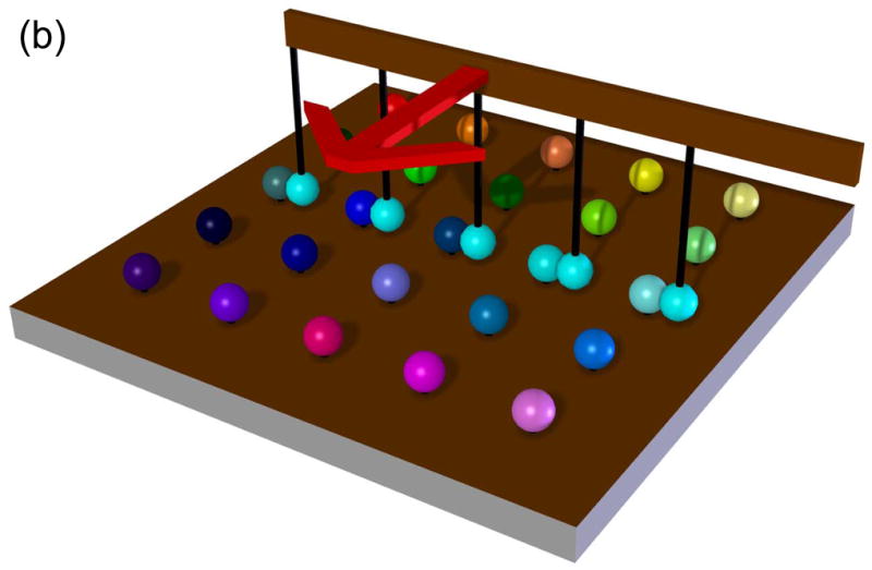
Rapid screening with DIBs. (a) Proof of principle experiment demonstrating the screening of pore blockers. A droplet containing wild-type αHL heptamers was placed on a movable electrode, while a second branched electrode was common to three analyte droplets. The first analyte droplet contained only buffer: 10 mM MOPS, 1 M KCl, pH 7.0. The second droplet contained 50 μM βCD and the third 50 μM heptakis(2,3,6-tri-O-methyl)-β-cyclodextrin (TRIMEB), in the same buffer. The αHL droplet was connected to the first analyte droplet. Pore insertions were manifested as stepwise increases in ionic current at −50 mV. The αHL droplet was then disconnected from the first droplet and moved to the second. The binding of βCD to the pores is visible as transient current blockades superimposed on the current steps caused by pore insertion. The αHL droplet was then connected to the third droplet. TRIMEB caused a larger current block than βCD, with different kinetics. Finally, the αHL droplet was reconnected to the first droplet and no binding events were observed. Reprinted with permission from J. Am. Chem. Soc. 2007, 129, 8650–8655. Copyright 2007 Am. Chem. Soc. (b) Hypothetical device for rapid screening of droplets versus droplets using the “snap-on/snap-off” process demonstrated on a smaller scale in (a). (c) A second hypothetical device in which a collection of ion channels (in an array of droplets) is screened with a collection of drugs presented as an array in a hydrated support. (d) A third hypothetical screening device in which DIBs are formed and broken in rapid succession in a microfluidic device.
Rapid screening with DIBs. (a) Proof of principle experiment demonstrating the screening of pore blockers. A droplet containing wild-type αHL heptamers was placed on a movable electrode, while a second branched electrode was common to three analyte droplets. The first analyte droplet contained only buffer: 10 mM MOPS, 1 M KCl, pH 7.0. The second droplet contained 50 μM βCD and the third 50 μM heptakis(2,3,6-tri-O-methyl)-β-cyclodextrin (TRIMEB), in the same buffer. The αHL droplet was connected to the first analyte droplet. Pore insertions were manifested as stepwise increases in ionic current at −50 mV. The αHL droplet was then disconnected from the first droplet and moved to the second. The binding of βCD to the pores is visible as transient current blockades superimposed on the current steps caused by pore insertion. The αHL droplet was then connected to the third droplet. TRIMEB caused a larger current block than βCD, with different kinetics. Finally, the αHL droplet was reconnected to the first droplet and no binding events were observed. Reprinted with permission from J. Am. Chem. Soc. 2007, 129, 8650–8655. Copyright 2007 Am. Chem. Soc. (b) Hypothetical device for rapid screening of droplets versus droplets using the “snap-on/snap-off” process demonstrated on a smaller scale in (a). (c) A second hypothetical device in which a collection of ion channels (in an array of droplets) is screened with a collection of drugs presented as an array in a hydrated support. (d) A third hypothetical screening device in which DIBs are formed and broken in rapid succession in a microfluidic device.

Rapid screening with DIBs. (a) Proof of principle experiment demonstrating the screening of pore blockers. A droplet containing wild-type αHL heptamers was placed on a movable electrode, while a second branched electrode was common to three analyte droplets. The first analyte droplet contained only buffer: 10 mM MOPS, 1 M KCl, pH 7.0. The second droplet contained 50 μM βCD and the third 50 μM heptakis(2,3,6-tri-O-methyl)-β-cyclodextrin (TRIMEB), in the same buffer. The αHL droplet was connected to the first analyte droplet. Pore insertions were manifested as stepwise increases in ionic current at −50 mV. The αHL droplet was then disconnected from the first droplet and moved to the second. The binding of βCD to the pores is visible as transient current blockades superimposed on the current steps caused by pore insertion. The αHL droplet was then connected to the third droplet. TRIMEB caused a larger current block than βCD, with different kinetics. Finally, the αHL droplet was reconnected to the first droplet and no binding events were observed. Reprinted with permission from J. Am. Chem. Soc. 2007, 129, 8650–8655. Copyright 2007 Am. Chem. Soc. (b) Hypothetical device for rapid screening of droplets versus droplets using the “snap-on/snap-off” process demonstrated on a smaller scale in (a). (c) A second hypothetical device in which a collection of ion channels (in an array of droplets) is screened with a collection of drugs presented as an array in a hydrated support. (d) A third hypothetical screening device in which DIBs are formed and broken in rapid succession in a microfluidic device.
Rapid screening with DIBs. (a) Proof of principle experiment demonstrating the screening of pore blockers. A droplet containing wild-type αHL heptamers was placed on a movable electrode, while a second branched electrode was common to three analyte droplets. The first analyte droplet contained only buffer: 10 mM MOPS, 1 M KCl, pH 7.0. The second droplet contained 50 μM βCD and the third 50 μM heptakis(2,3,6-tri-O-methyl)-β-cyclodextrin (TRIMEB), in the same buffer. The αHL droplet was connected to the first analyte droplet. Pore insertions were manifested as stepwise increases in ionic current at −50 mV. The αHL droplet was then disconnected from the first droplet and moved to the second. The binding of βCD to the pores is visible as transient current blockades superimposed on the current steps caused by pore insertion. The αHL droplet was then connected to the third droplet. TRIMEB caused a larger current block than βCD, with different kinetics. Finally, the αHL droplet was reconnected to the first droplet and no binding events were observed. Reprinted with permission from J. Am. Chem. Soc. 2007, 129, 8650–8655. Copyright 2007 Am. Chem. Soc. (b) Hypothetical device for rapid screening of droplets versus droplets using the “snap-on/snap-off” process demonstrated on a smaller scale in (a). (c) A second hypothetical device in which a collection of ion channels (in an array of droplets) is screened with a collection of drugs presented as an array in a hydrated support. (d) A third hypothetical screening device in which DIBs are formed and broken in rapid succession in a microfluidic device.

“O-U” DIB network. (a) A twenty-six droplet DIB network in the form of “O-U” (Oxford University). Each 200 nL droplet contains 120 ng/mL αHL heptamer in buffer (10 mM MOPS, 1 M KCl, pH 7.0) except the pink droplet in the middle, which contains 55 ng/mL αHL heptamer, 23 μM TRIMEB, and a small amount of tetramethylrhodamine (pink) in buffer. Pores became incorporated into the bilayers at each droplet interface. Two Ag/AgCl electrodes connected to micromanipulators were inserted into the droplets on the bottom left and top right corners of the network and wired to a patch-clamp amplifier to enable electrical recording. Removal and insertion of these electrodes into other droplets is straightforward. (b) Current trace with an applied potential of −50 mV. Blocking events are observed that differ from the typical “square-waves” seen with individual lipid bilayers. Adapted with permission from J. Am. Chem. Soc. 2007, 129, 11854–11865. Copyright 2007 Am. Chem. Soc.

Comparison of a DIB network with equivalent circuit. (a) Single DIB system in which Droplet L contains 1.7 ng/mL αHL heptamer and droplet R contains 10 μM TRIMEB, both dissolved in buffer (10 mM MOPS, 1 M KCl, pH 7.0). The potential is applied to Droplet R and Droplet L is grounded. The pores insert with the cap domain in Droplet L and the β barrel in the bilayer. An experimental current trace is shown arising from a single αHL pore in a DIB at an applied potential of −50 mV. The arrow indicates the insertion of the pore. One non-covalent blocking event by TRIMEB is shown. Notice that blocking events in single bilayers exhibit square steps. Levels 1 and 2 indicate the states in which the pore is blocked by TRIMEB and the unblocked pore, respectively. (b) Simple double DIB network in which Droplet L contains buffer (10 mM MOPS, 1 M KCl, pH 7.0), M contains 1.7 ng/mL αHL heptamer in buffer, and R contains 10 μM TRIMEB in buffer. The potential is applied to Droplet R and Droplet L is grounded. The current is measured from Droplet R to Droplet L. The pores insert into the two membranes with opposing orientations as shown. (c) Experimental current trace of a transient TRIMEB blocking event when there is a single pore in each bilayer of the arrangement shown in (b). Notice the curvature in the trace. The applied potential is −50 mV. The overlaid plot of current versus time was derived by applying Kirchhoff’s laws to the equivalent circuit, which is depicted in panel (d). The following parameter values are assigned: RA = 0.9 GΩ, R = 1 GΩ,
(open), R* = 9 GΩ, CA = 350 pF, and CB = 500 pF. (d) Schematic of the equivalent circuit for analysis of blocking events in a double DIB system with any bilayer-pore configuration. We assume that only one pore in bilayer B is blocked at a time. CA is the capacitance and RA is the net resistance of bilayer A (all pores in bilayer A combined). CB is the capacitance of bilayer B,
is the net resistance of bilayer B excluding one pore (all pores in bilayer B combined except one that interacts with the blocker), R represents a single pore in bilayer B that interacts with the blocker, and R* represents the state when the blocker has interacted with pore R. Opening the switch in the circuit simulates the binding of the blocker to the pore, and closing the switch simulates the dissociation of the blocker from the pore. If there is only one pore in bilayer B, we set
to an infinite resistance. Adapted with permission from J. Am. Chem. Soc. 2007, 129, 11854–11865. Copyright 2007 Am. Chem. Soc.

A battery powered by a concentration gradient. (a) Three droplets in a row form two DIBs. The right two droplets contain a 1 M NaCl solution, while the left droplet contains a 100 mM NaCl solution. The N123R αHL mutant in the left DIB is anion selective, which allows a greater chloride ion flux from the middle to left droplet relative to the sodium ion flux. (b) The self-generated voltage powers the flow of ions through the system, thereby enabling the investigation of binding events at the right DIB. Here, we observe βCD binding reversibly to the M113F/K147N αHL mutant. Adapted with permission from J. Am. Chem. Soc. 2007, 129, 8650–8655. Copyright 2007 Am. Chem. Soc.

Mimicking a sensory system with a droplet network. (a) Three droplets containing the light-driven proton pump bacteriorhodopsin, solubilized in 0.001% dodecylmaltoside, surround a central droplet containing buffer. On the left, an αHL-containing droplet completes the electrical circuit. Upon irradiation with a green laser, thousands of bacteriorhodopsin proteins in each DIB move protons (positive charge) across their respective bilayers. (b) This is manifested as a spike in the ionic current flowing through the system, which stops when the laser is turned off. This simple network “sees” light, and generates a signal that can be interpreted (in this case by a computer). Reprinted with permission from J. Am. Chem. Soc. 2007, 129, 8650–8655. Copyright 2007 Am. Chem. Soc.

In vitro transcription and translation (IVTT) to form a functional αHL pore inside a droplet. (a) The cis droplet contained the IVTT mix, DNA (400 ng/μL) and DPhPC (1.4 mM) vesicles in 10 mM HEPES buffer, 250 mM KCl at pH 7.0. The trans droplet contained DPhPC (1.4 mM) vesicles in the same buffer with γCD (10 μM). The IVTT mix includes all the components necessary for transcription and translation. The oil was a mixture of hexadecane and decane in a 10:1 ratio. (b) Visualization of an SDS-polyacrylamide gel by autoradiography showing protein expression after different time intervals. (c) Current trace showing the insertion of a WT αHL pore (arrow) followed by blockades (60% of current) representing γCD binding.
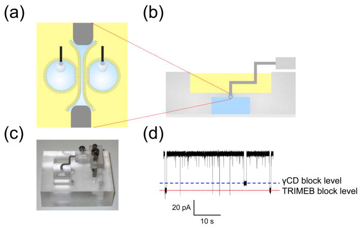
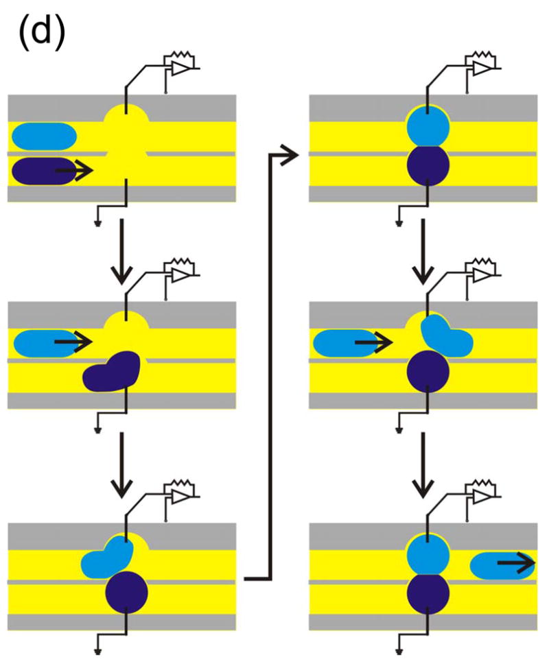
Formation of a double bilayer. (a) A schematic cross-sectional enlargement of a water film stretched across the aperture of a Ag/AgCl wand, illustrating the formation of a double bilayer between two opposed aqueous droplets and an aqueous film. The two gray blocks at the top and bottom represent the surface of the wand. The droplets can be replaced with agarose spheres if greater mechanical rigidity is desired. (b) Schematic cross-section of the chamber used to form double bilayers. A dipping mechanism moves the Ag/AgCl wand between the upper oil-lipid bath and the lower aqueous reservoir. The aperture of the wand acquires a thin water film. (c) Dipping mechanism of the double bilayer platform. The wand is pressed down through the slot and into the aqueous chamber and held with a screw. To bring the water film-coated wand back into the oil-lipid bath, the screw is loosened and springs provide a restoring force. (d) A double bilayer was formed with 5 μM TRIMEB in one 2.5% (w/v) agarose sphere and 5 μM γCD in the other, and a water film containing 2 ng/mL WT αHL. The current trace exhibits both TRIMEB (larger amplitude) and γCD (lower amplitude) blocks at an applied potential of +50 mV.
References
Publication types
MeSH terms
Substances
Grants and funding
LinkOut - more resources
Full Text Sources
Other Literature Sources