

Development and implantation of a minimally invasive wireless subretinal neurostimulator
- PMID: 19403357
- PMCID: PMC7444418
- DOI: 10.1109/TBME.2009.2021401
Development and implantation of a minimally invasive wireless subretinal neurostimulator
Abstract
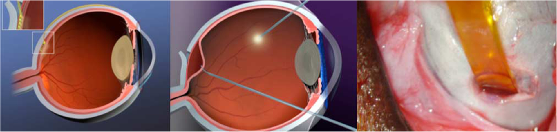
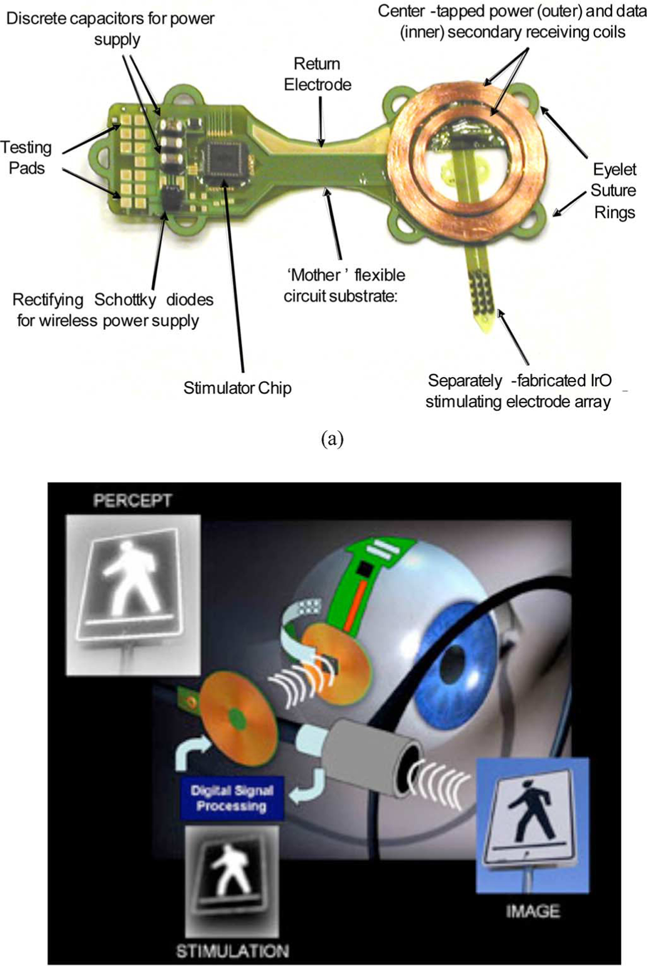
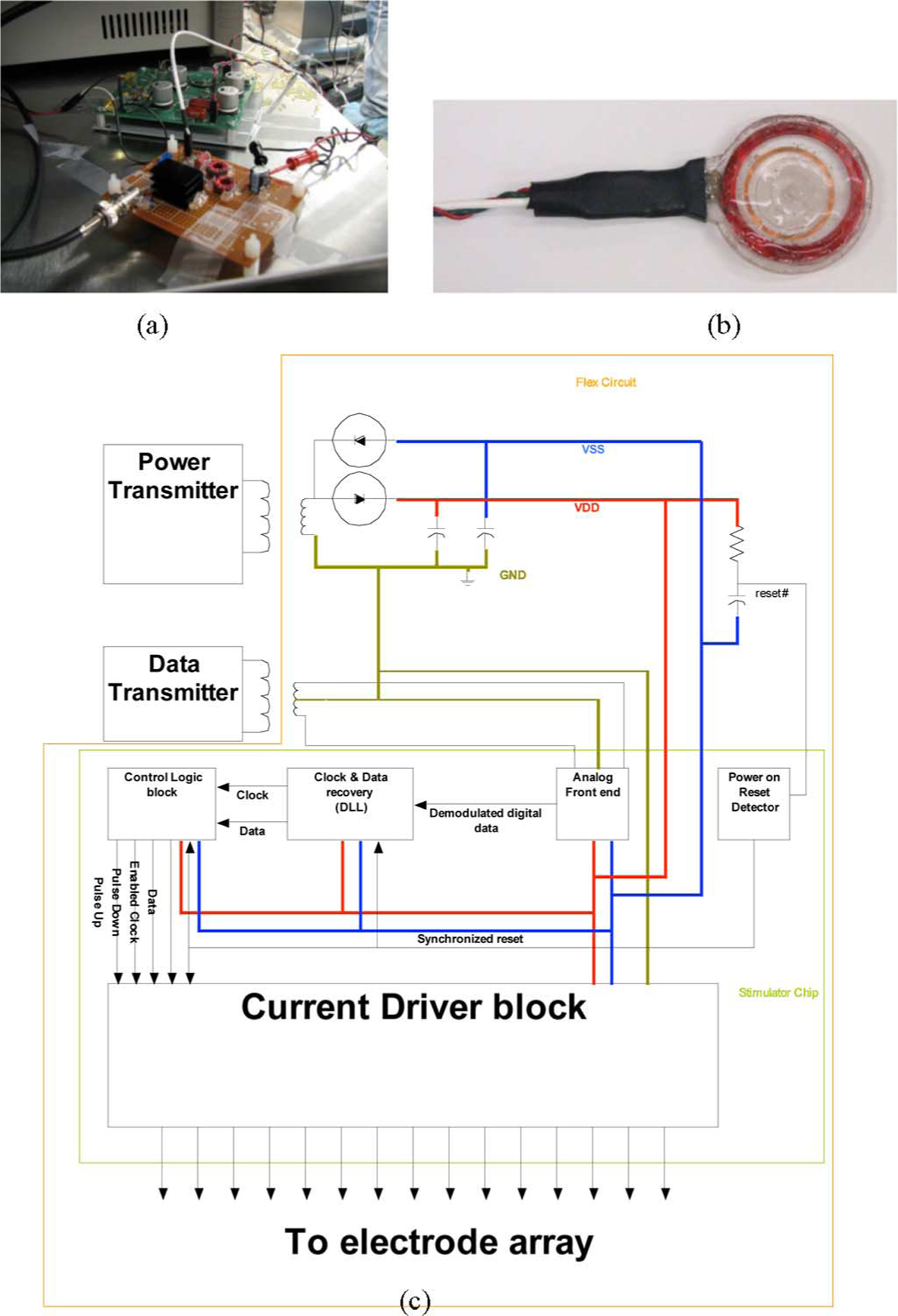
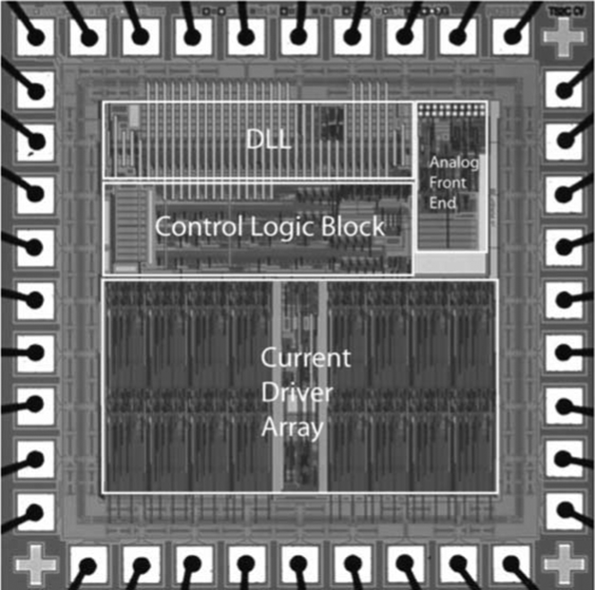
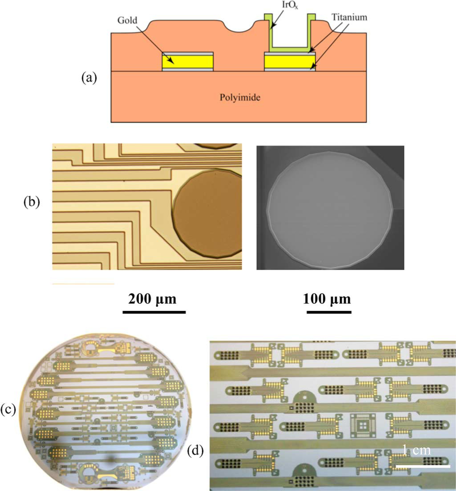
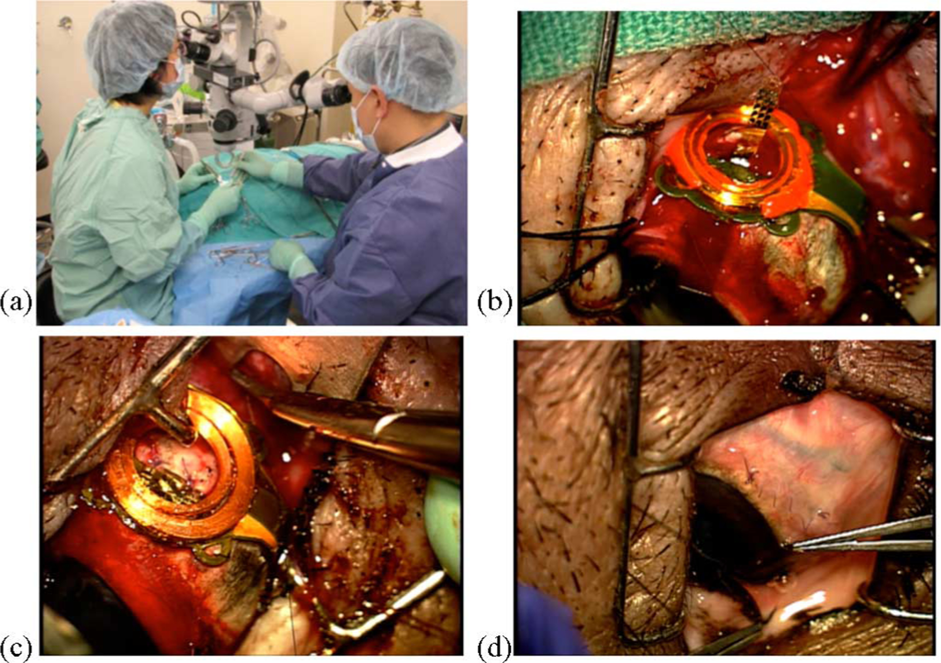
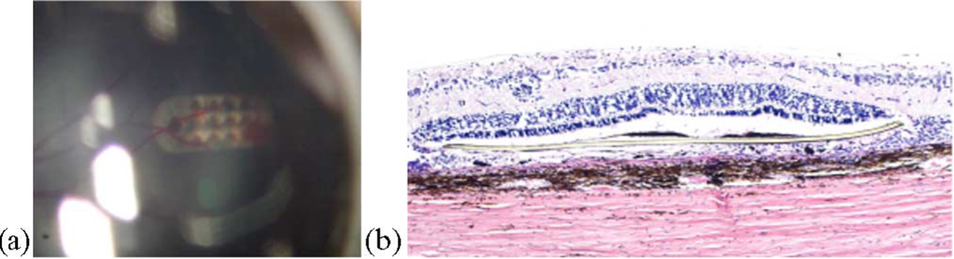
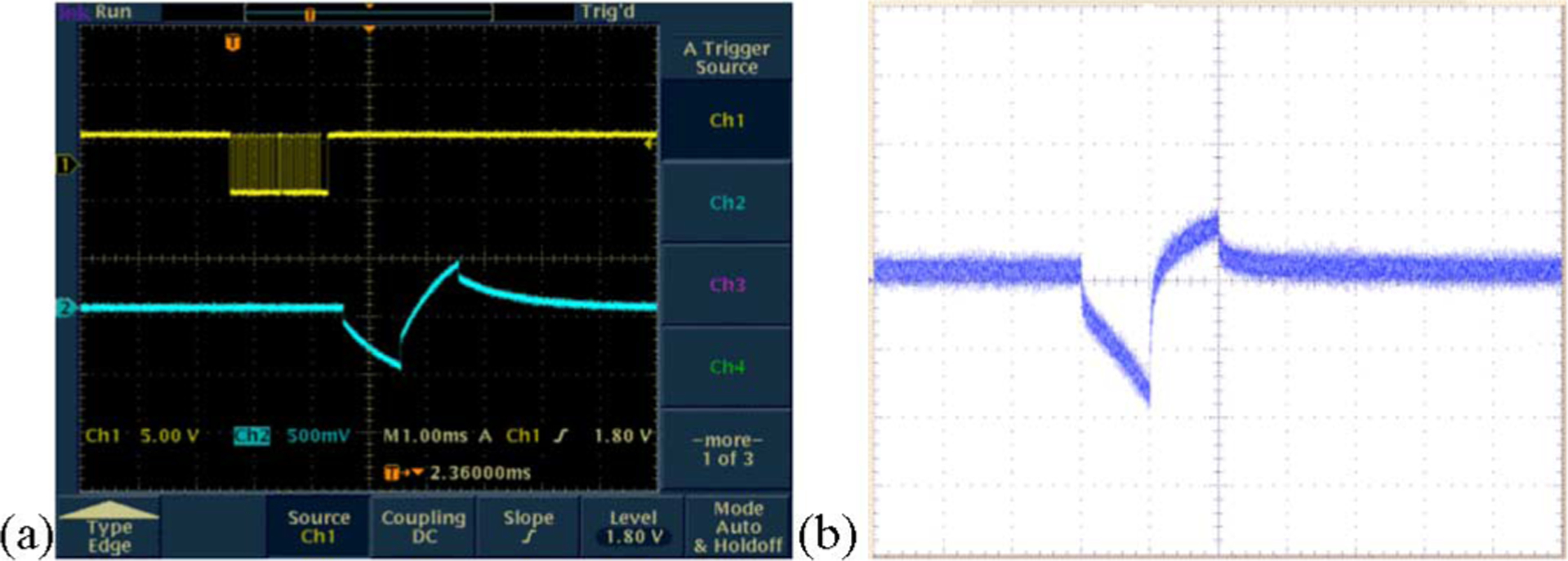
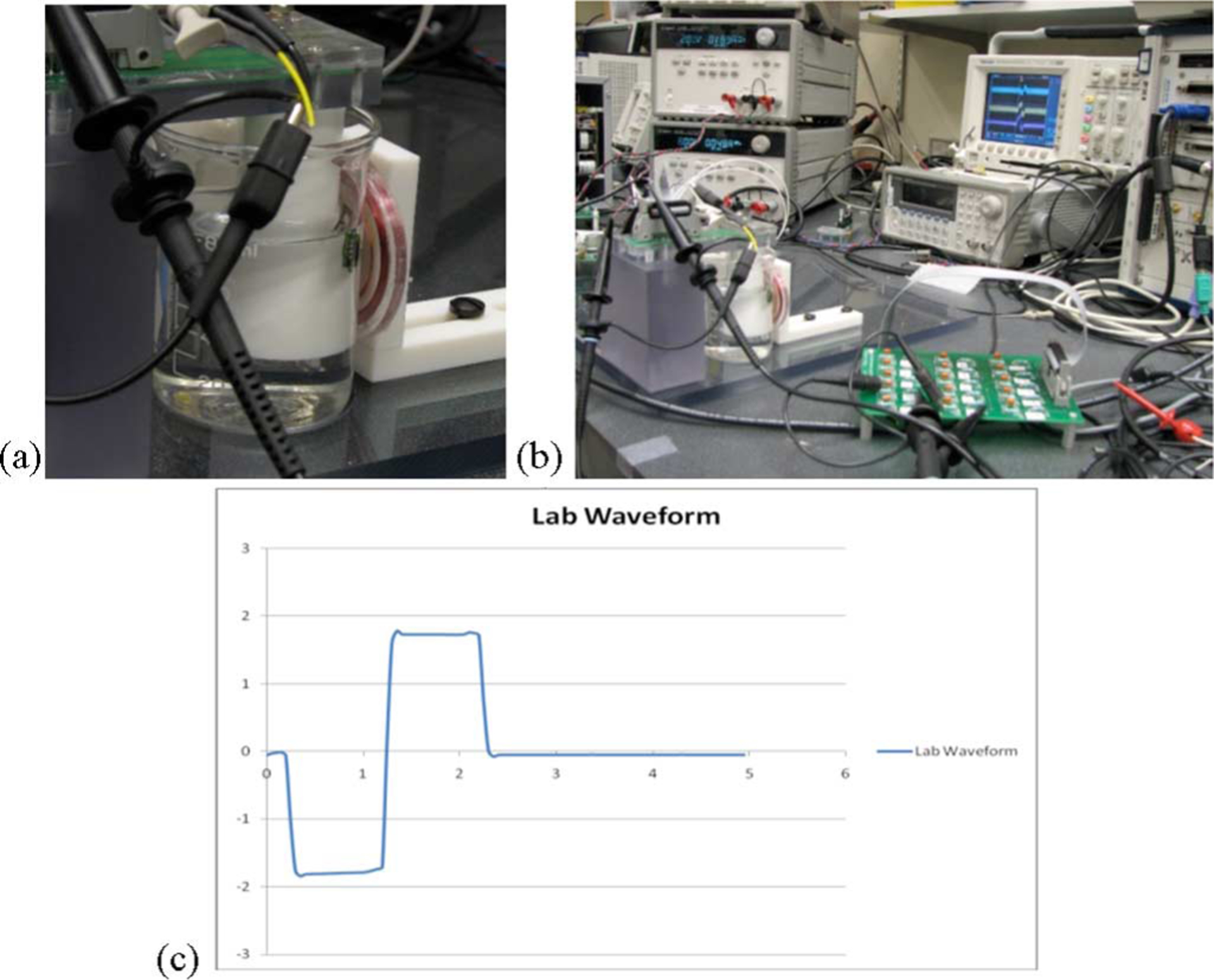
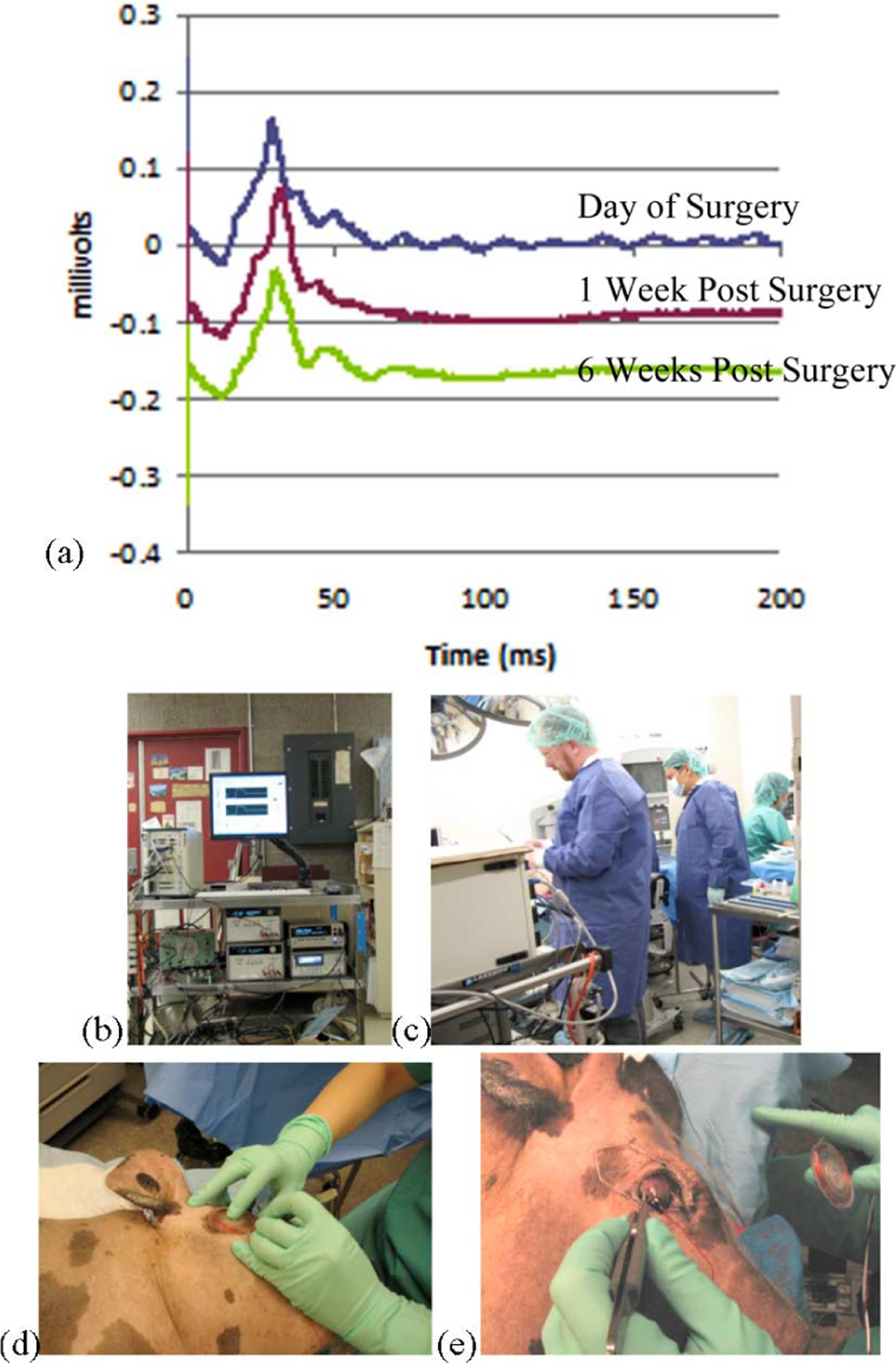
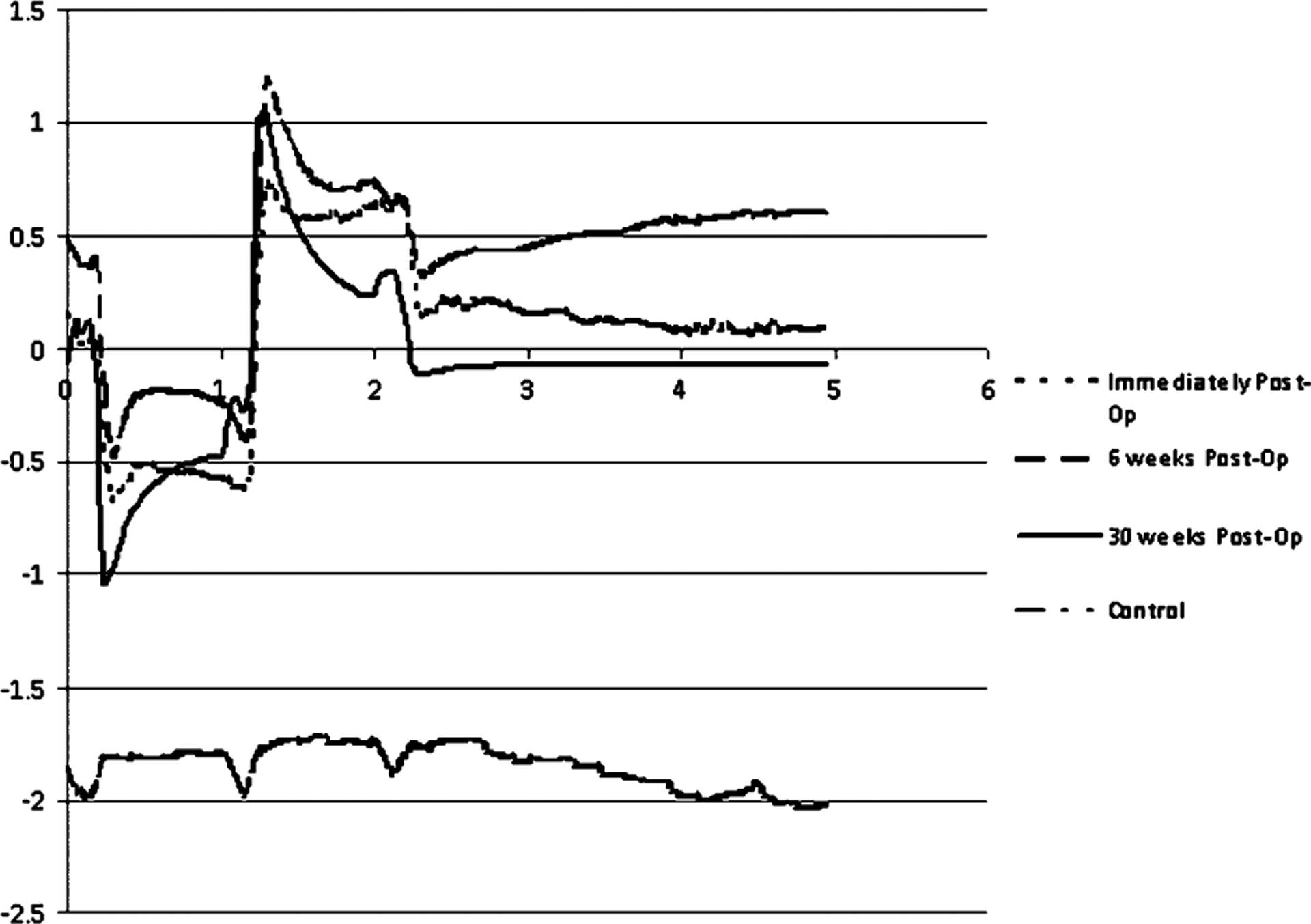
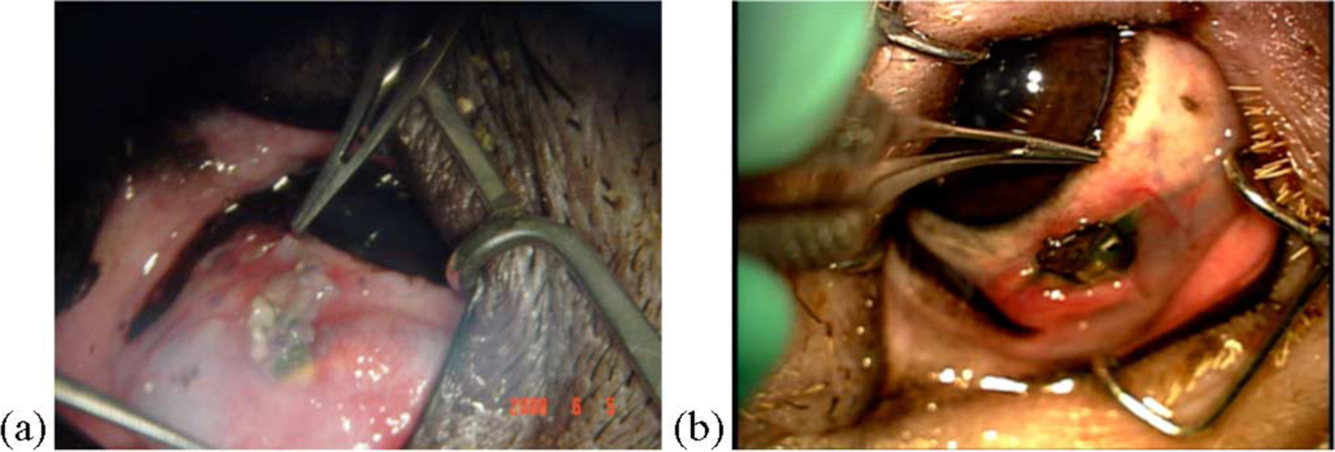
A wirelessly operated, minimally invasive retinal prosthesis was developed for preclinical chronic implantation studies in Yucatan minipig models. The implant conforms to the outer wall of the eye and drives a microfabricated polyimide stimulating electrode array with sputtered iridium oxide electrodes. This array is implanted in the subretinal space using a specially designed ab externo surgical technique that fixes the bulk of the prosthesis to the outer surface of the sclera. The implanted device is fabricated on a host polyimide flexible circuit. It consists of a 15-channel stimulator chip, secondary power and data receiving coils, and discrete power supply components. The completed device is encapsulated in poly(dimethylsiloxane) except for the reference/counter electrode and the thin electrode array. In vitro testing was performed to verify the performance of the system in biological saline using a custom RF transmitter circuit and primary coils. Stimulation patterns as well as pulse strength, duration, and frequency were programmed wirelessly using custom software and a graphical user interface. Wireless operation of the retinal implant has been verified both in vitro and in vivo in three pigs for more than seven months, the latter by measuring stimulus artifacts on the eye surface using contact lens electrodes.
Figures
Similar articles
-
A hermetic wireless subretinal neurostimulator for vision prostheses.IEEE Trans Biomed Eng. 2011 Nov;58(11):3197-205. doi: 10.1109/TBME.2011.2165713. Epub 2011 Aug 22. IEEE Trans Biomed Eng. 2011. PMID: 21859595 Free PMC article.
-
Realization of a 15-channel, hermetically-encased wireless subretinal prosthesis for the blind.Annu Int Conf IEEE Eng Med Biol Soc. 2009;2009:200-3. doi: 10.1109/IEMBS.2009.5333619. Annu Int Conf IEEE Eng Med Biol Soc. 2009. PMID: 19964209 Free PMC article.
-
Implantation and testing of subretinal film electrodes in domestic pigs.Exp Eye Res. 2006 Feb;82(2):332-40. doi: 10.1016/j.exer.2005.07.007. Epub 2005 Aug 25. Exp Eye Res. 2006. PMID: 16125172
-
A new approach towards a minimal invasive retina implant.J Neural Eng. 2007 Mar;4(1):S30-7. doi: 10.1088/1741-2560/4/1/S05. Epub 2007 Feb 20. J Neural Eng. 2007. PMID: 17325414 Review.
-
[Review of the design of power supply in retinal implants].Sheng Wu Yi Xue Gong Cheng Xue Za Zhi. 2008 Aug;25(4):954-7. Sheng Wu Yi Xue Gong Cheng Xue Za Zhi. 2008. PMID: 18788317 Review. Chinese.
Cited by
-
Building the bionic eye: an emerging reality and opportunity.Prog Brain Res. 2011;192:3-15. doi: 10.1016/B978-0-444-53355-5.00001-4. Prog Brain Res. 2011. PMID: 21763515 Free PMC article. Review.
-
Communication and Control System for a 15-Channel Hermetic Retinal Prosthesis.Biomed Signal Process Control. 2011 Oct 1;6(4):356-363. doi: 10.1016/j.bspc.2011.05.007. Biomed Signal Process Control. 2011. PMID: 21927618 Free PMC article.
-
Responses to pulsatile subretinal electric stimulation: effects of amplitude and duration.J Neurophysiol. 2013 Apr;109(7):1954-68. doi: 10.1152/jn.00293.2012. Epub 2013 Jan 23. J Neurophysiol. 2013. PMID: 23343891 Free PMC article.
-
A hermetic wireless subretinal neurostimulator for vision prostheses.IEEE Trans Biomed Eng. 2011 Nov;58(11):3197-205. doi: 10.1109/TBME.2011.2165713. Epub 2011 Aug 22. IEEE Trans Biomed Eng. 2011. PMID: 21859595 Free PMC article.
-
A high frequency active voltage doubler in standard CMOS using offset-controlled comparators for inductive power transmission.IEEE Trans Biomed Circuits Syst. 2013 Jun;7(3):213-24. doi: 10.1109/TBCAS.2012.2198649. IEEE Trans Biomed Circuits Syst. 2013. PMID: 23853321 Free PMC article.
References
-
- Zhou JA, Woo SJ, Park SI, Kim ET, Seo JM, Chung H, and Kim SJ, “A suprachoroidal electrical retinal stimulator design for long-term animal experiments and in-vivo assessment of its feasibility and biocompatibility in rabbits,” J. Biomed. Biotech, vol. 2008, pp. 547428-1–547428-10, 2008. - PMC - PubMed
-
- Schanze T, Hesse L, Lau C, Greve N, Haberer W, Kammer S, Doerge T, Rentzos A, and Stieglitz T, “An optically powered single-channel stimulation implant as test system for chronic biocompatibility and biostability of miniaturized retinal vision prostheses,” IEEE Trans. Biomed. Eng, vol. 54, no. 6, pp. 983–992, June 2007. - PubMed
-
- Yanai D, Weiland JD, Mahadevappa M, Greenberg RJ, Fine I, and Humayun MS, “Visual performance using a retinal prosthesis in three subjects with retinitis pigmentosa,” Amer. J. Ophthalmol, vol. 143, pp. 820–827, 2007. - PubMed
-
- Wong YT, Dommel N, Preston P, Hallum LE, Lehmann T, Lovell NH, and Suaning GJ, “Retinal neurostimulator for a multifocal vision prosthesis,” IEEE Trans. Neural Syst. Rehabil. Eng, vol. 15, no. 3, pp. 425–434, September 2007. - PubMed
Publication types
MeSH terms
Grants and funding
LinkOut - more resources
Full Text Sources
Other Literature Sources
