. 2009 Jun 2;106(22):8811-7.
doi: 10.1073/pnas.0900561106. Epub 2009 Apr 30.

Magnetic stabilization and vorticity in submillimeter paramagnetic liquid tubes

Affiliations

Magnetic stabilization and vorticity in submillimeter paramagnetic liquid tubes

J Michael D Coey et al. Proc Natl Acad Sci U S A. .

Abstract

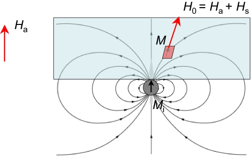
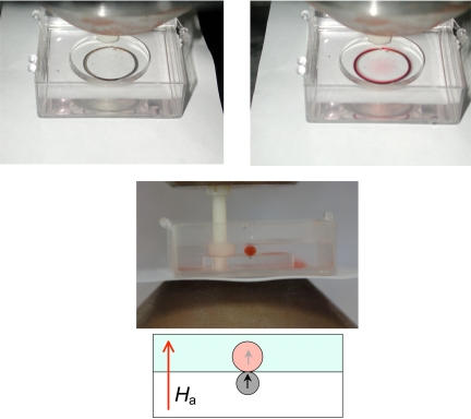
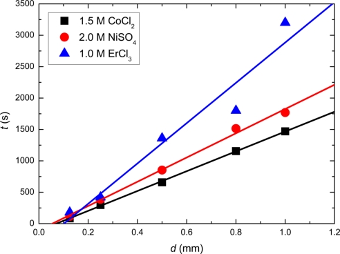
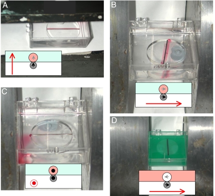
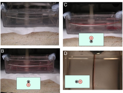
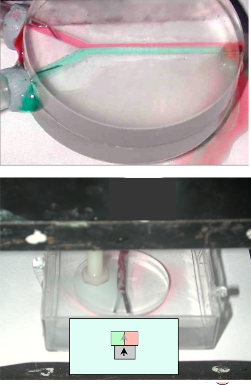
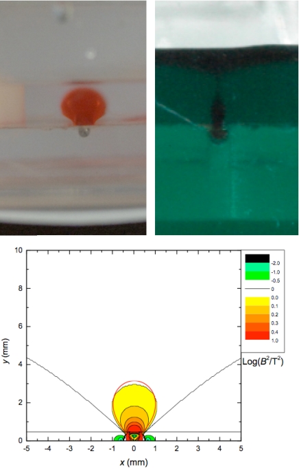
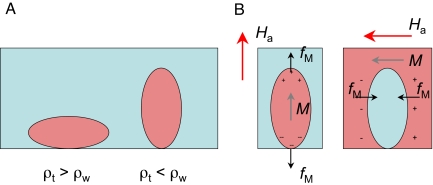
It is possible to suppress convection and dispersion of a paramagnetic liquid by means of a magnetic field. A tube of paramagnetic liquid can be stabilized in water along a ferromagnetic track in a vertical magnetic field, but not in a horizontal field. Conversely, an "antitube" of water can be stabilized in a paramagnetic liquid along the same track in a transverse horizontal field, but not in a vertical field. The stability arises from the interaction of the induced moment in the solution with the magnetic field gradient in the vicinity of the track. The magnetic force causes the tube of paramagnetic liquid to behave as if it were encased by an elastic membrane whose cross-section is modified by gravitational forces and Maxwell stress. Convection from the tube to its surroundings is inhibited, but not diffusion. Liquid motion within the paramagnetic tube, however, exhibits vorticity in tubes of diameter 1 mm or less--conditions where classical pipe flow would be perfectly streamline, and mixing extremely slow. The liquid tube is found to slide along the track almost without friction. Paramagnetic liquid tubes and antitubes offer appealing new prospects for mass transport, microfluidics, and electrodeposition.


Conflict of interest statement

The authors declare no conflict of interest.

Figures

Fig. 1.
Fig. 1.
The different magnetic fields and magnetizations involved in the experiments. M is the magnetization of an element of liquid, Mi is the magnetization of the iron track, Ha is the uniform field applied by using a permanent magnet or an electromagnet, Hs is the stray field created by Mi, and H0 = Ha + Hs is the magnetic field acting on M. The demagnetizing field Hd is very small in M, but not in Mi.
Fig. 2.
Fig. 2.
Formation and cross section of paramagnetic liquid tubes. A circular iron track embedded in a Lucite disc, immersed in water and placed in a vertical magnetic field of 0.5 T (Upper Left). When a 1.5 M CoCl2 solution is injected near the track it does not disperse, but forms a paramagnetic liquid tube along the track (Upper Right). (Lower) The cross-section of a straight tube of 1 M ErCl3 in a vertical field of 1 T.
Fig. 3.
Fig. 3.
Time taken for a magnetically-confined paramagnetic liquid tube of 1.5 M CoCl2, 2.0 M NiSo4, and 1.0 M ErCl3 to diffuse away in water, plotted against the diameter of the iron track, d = 2ri.
Fig. 4.
Fig. 4.
Stable and unstable configurations for paramagnetic liquid tubes. Configurations where magnetic confinement of a liquid can be achieved are a tube in a vertical field (A) and an antitube in a horizontal field (D). The water is dyed black in D for visibility. The paramagnetic liquid is colored pink in the diagrams, and the water pale blue. The magnetization of the iron wire is indicated by the black arrow, and that of the paramagnetic liquid by the gray arrow. The water in D has an effective moment indicated by the gray arrow. Dipole forces are attractive in A and D but repulsive in B and C.
Fig. 5.
Fig. 5.
Paramagnetic liquid tubes stabilized by an immersed track. (A) An iron wire immersed in water. (B–D) Stable positions for a paramagnetic liquid tube are above (C) and below (B) the ferromagnetic wire in a vertical field, and at either side of it in a horizontal field (D). The photographs show tubes of ErCl3 in water.
Fig. 6.
Fig. 6.
Comparison of streamline flow of two paramagnetic liquids colored red and green in a transparent rectangular channel (Upper) and vortex flow (Lower) in a paramagnetic liquid tube with the same dimensions.
Fig. 7.
Fig. 7.
Observed and calculated cross-sections. Cross-sections of a paramagnetic liquid tube (Upper Left), and an antitube (Upper Right). In Upper Left the Maxwell stress and gravitational deformations tend to cancel, whereas in Upper Right they add. (Lower) Constant energy surfaces for a 0.5-mm iron wire calculated numerically; the profile corresponding to the analytical approximation of Eq. 12 is indicated by the red line.
Fig. 8.
Fig. 8.
Schematic illustration of the deformations of a liquid tube due to density differences (A), and Maxwell stress on a paramagnetic liquid tube (B Left) and on an antitube (B Right).

References

    1. Cussler EL. Diffusion, Mass Transfer in Fluid Systems. Cambridge, UK: Cambridge Univ Press; 1997. pp. 142–154.
    1. Landau LD, Lifschitz EM. Electrodynamics of Continuous Media. Oxford: Pergamon; 1984. pp. 126–128.
    1. Rosensweig A. Ferrohydrodynamics. New York: Dover; 1997. pp. 13pp. 25–31.pp. 110–118.
    1. Boyer TH. The force on a magnetic dipole. Am J Phys. 1988;56:688–691.
    1. Coey JMD. Magnetism and Magnetic Materials. Cambridge, UK: Cambridge Univ Press; 2009. in press.

Publication types

LinkOut - more resources