Optical neuronal guidance in three-dimensional matrices
- PMID: 19428538
- PMCID: PMC3819723
- DOI: 10.1016/j.jneumeth.2009.02.004
Optical neuronal guidance in three-dimensional matrices
Abstract
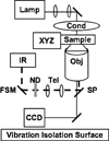
We demonstrate effective guidance of neurites extending from PC12 cells in a three-dimensional collagen matrix using a focused infrared laser. Processes can be redirected in an arbitrarily chosen direction in the imaging plane in approximately 30 min with an 80% success rate. In addition, the application of the laser beam significantly increases the rate of neurite outgrowth. These results extend previous observations on 2D coated glass coverslips. We find that the morphology of growth cones is very different in 3D than in 2D, and that this difference suggests that the filopodia play a key role in optical guidance. This powerful, flexible, non-contact guidance technique has potentially broad applications in tissues and engineered environments.
Figures


Similar articles
-
Automated laser guidance of neuronal growth cones using a spatial light modulator.J Biophotonics. 2009 Nov;2(11):682-92. doi: 10.1002/jbio.200910043. J Biophotonics. 2009. PMID: 19705368
-
A rolled sheet of collagen gel with cultured Schwann cells: model of nerve conduit to enhance neurite growth.J Biosci Bioeng. 2010 May;109(5):512-8. doi: 10.1016/j.jbiosc.2009.11.002. Epub 2009 Nov 25. J Biosci Bioeng. 2010. PMID: 20347776
-
Using PC12 cells to evaluate poly(caprolactone) and collagenous microcarriers for applications in nerve guide fabrication.Biotechnol Prog. 2003 Nov-Dec;19(6):1767-74. doi: 10.1021/bp034086m. Biotechnol Prog. 2003. PMID: 14656154
-
Neural regenerative strategies incorporating biomolecular axon guidance signals.Ann Biomed Eng. 2012 Mar;40(3):578-97. doi: 10.1007/s10439-011-0505-0. Epub 2012 Jan 5. Ann Biomed Eng. 2012. PMID: 22218702 Review.
-
Nanostructured scaffolds for neural applications.Nanomedicine (Lond). 2008 Apr;3(2):183-99. doi: 10.2217/17435889.3.2.183. Nanomedicine (Lond). 2008. PMID: 18373425 Review.
Cited by
-
Infrared Laser Effects on Cell Projection Depend on Irradiation Intermittence and Cell Activity.Cells. 2023 Feb 8;12(4):540. doi: 10.3390/cells12040540. Cells. 2023. PMID: 36831208 Free PMC article.
-
Near-infrared low-level laser stimulation of telocytes from human myometrium.Lasers Med Sci. 2014 Nov;29(6):1867-74. doi: 10.1007/s10103-014-1589-1. Epub 2014 May 29. Lasers Med Sci. 2014. PMID: 24870411 Free PMC article.
-
Triggering of high-speed neurite outgrowth using an optical microheater.Sci Rep. 2015 Nov 16;5:16611. doi: 10.1038/srep16611. Sci Rep. 2015. PMID: 26568288 Free PMC article.
-
Effects of near infrared focused laser on the fluorescence of labelled cell membrane.Sci Rep. 2018 Dec 5;8(1):17674. doi: 10.1038/s41598-018-36010-1. Sci Rep. 2018. PMID: 30518772 Free PMC article.
-
Optical Tweezers Exploring Neuroscience.Front Bioeng Biotechnol. 2020 Nov 27;8:602797. doi: 10.3389/fbioe.2020.602797. eCollection 2020. Front Bioeng Biotechnol. 2020. PMID: 33330435 Free PMC article. Review.
References
-
- Balgude AP, Yu X, Szymanski A, Bellamkonda RV. Agarose gel stiffness determines rate of DRG neurite extension in 3D cultures. Biomaterials. 2001;22:1077–1084. - PubMed
-
- Betz T, Koch D, Stuhrmann B, Ehrlicher A, Käs J. Statistical analysis of neuronal growth: edge dynamics and the effect of a focused laser on growth conemotility. New J Phys. 2007;9:426.
-
- Carnegie DJ, Stevenson DJ, Mazilu M, Gun-Moore F, Dholakia K. Guided neuronal growth using optical line traps. Opt Exp. 2008;16:10507. - PubMed
-
- Cukierman E, Pankov R, Stevens DR, Yamada KM. Taking cell-matrix adhesions to the third dimension. Science. 2001;294:1708–1712. - PubMed
-
- Cukierman E, Pankov R, Yamada KM. Cell interactions with three-dimensional matrices. Curr Opin Cell Biol. 2002;14:633–639. - PubMed
Publication types
MeSH terms
Substances
Grants and funding
LinkOut - more resources
Full Text Sources
Other Literature Sources

