

Patient-specific artery shrinkage and 3D zero-stress state in multi-component 3D FSI models for carotid atherosclerotic plaques based on in vivo MRI data
- PMID: 19444328
- PMCID: PMC2681261
Patient-specific artery shrinkage and 3D zero-stress state in multi-component 3D FSI models for carotid atherosclerotic plaques based on in vivo MRI data
Abstract
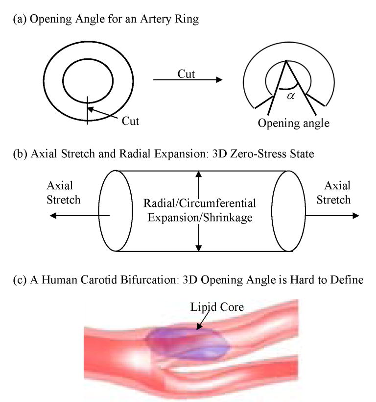
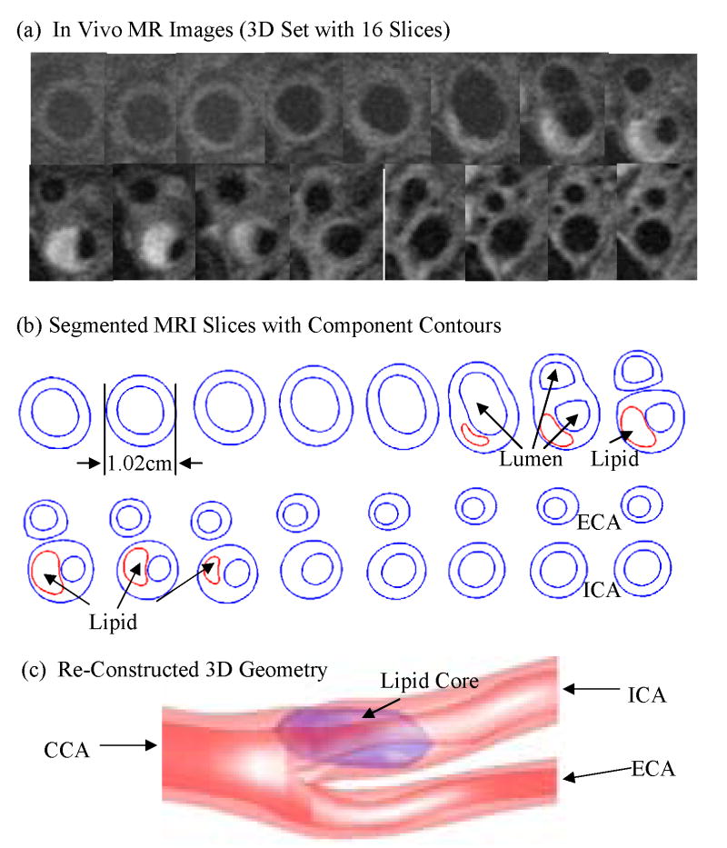
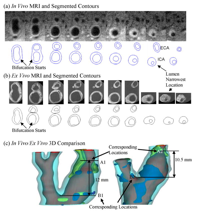
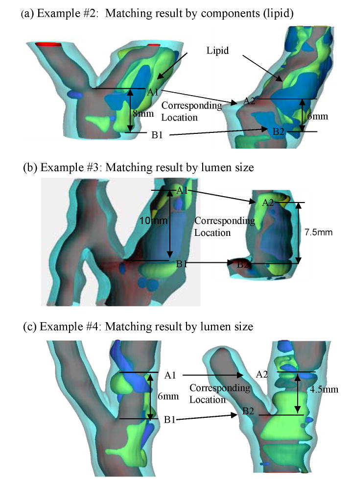
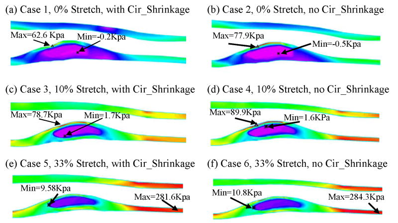
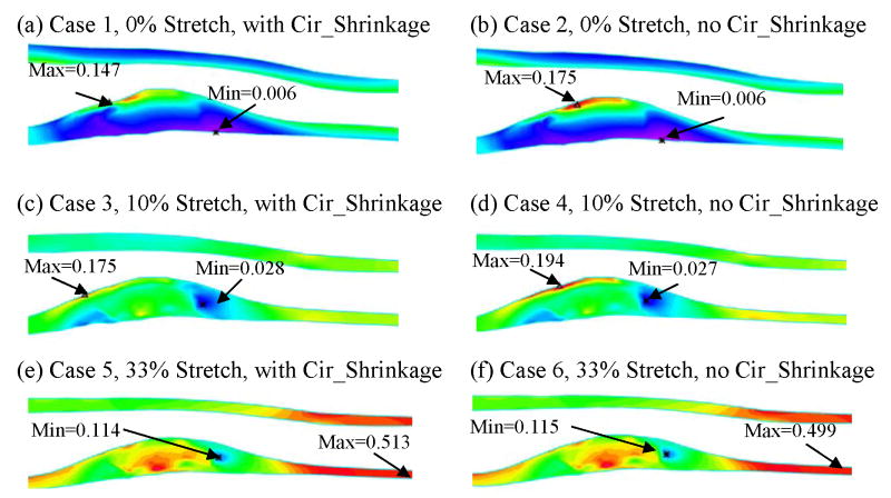
Image-based computational models for atherosclerotic plaques have been developed to perform mechanical analysis to quantify critical flow and stress/strain conditions related to plaque rupture which often leads directly to heart attack or stroke. An important modeling issue is how to determine zero stress state from in vivo plaque geometries. This paper presents a method to quantify human carotid artery axial and inner circumferential shrinkages by using patient-specific ex vivo and in vivo MRI images. A shrink-stretch process based on patient-specific in vivo plaque morphology and shrinkage data was introduced to shrink the in vivo geometry first to find the zero-stress state (opening angle was ignored to reduce the complexity), and then stretch and pressurize to recover the in vivo plaque geometry with computed initial stress, strain, flow pressure and velocity conditions. Effects of the shrink-stretch process on plaque stress/strain distributions were demonstrated based on patient-specific data using 3D models with fluid-structure interactions (FSI). The average artery axial and inner circumferential shrinkages were 25% and 7.9%, respectively, based on a data set obtained from 10 patients. Maximum values of maximum principal stress and strain increased 349.8% and 249% respectively with 33% axial stretch. Influence of inner circumferential shrinkage (7.9%) was not very noticeable under 33% axial stretch, but became more noticeable under smaller axial stretch. Our results indicated that accurate knowledge of artery shrinkages and the shrink-stretch process will considerably improve the accuracy of computational predictions made based on results from those in vivo MRI-based FSI models.
Keywords: Atherosclerosis; artery shrinkage; blood flow; carotid artery; fluid-structure interactions; vulnerable plaques.
Figures
Similar articles
-
3D MRI-based multicomponent FSI models for atherosclerotic plaques.Ann Biomed Eng. 2004 Jul;32(7):947-60. doi: 10.1023/b:abme.0000032457.10191.e0. Ann Biomed Eng. 2004. PMID: 15298432
-
Using in vivo Cine and 3D multi-contrast MRI to determine human atherosclerotic carotid artery material properties and circumferential shrinkage rate and their impact on stress/strain predictions.J Biomech Eng. 2012 Jan;134(1):011008. doi: 10.1115/1.4005685. J Biomech Eng. 2012. PMID: 22482663 Free PMC article.
-
3D MRI-based anisotropic FSI models with cyclic bending for human coronary atherosclerotic plaque mechanical analysis.J Biomech Eng. 2009 Jun;131(6):061010. doi: 10.1115/1.3127253. J Biomech Eng. 2009. PMID: 19449964 Free PMC article.
-
MRI strain imaging of the carotid artery: present limitations and future challenges.J Biomech. 2014 Mar 3;47(4):824-33. doi: 10.1016/j.jbiomech.2014.01.014. Epub 2014 Jan 13. J Biomech. 2014. PMID: 24468207 Review.
-
MRI-based biomechanical parameters for carotid artery plaque vulnerability assessment.Thromb Haemost. 2016 Mar;115(3):493-500. doi: 10.1160/TH15-09-0712. Epub 2016 Jan 21. Thromb Haemost. 2016. PMID: 26791734 Review.
Cited by
-
Multi-patient study for coronary vulnerable plaque model comparisons: 2D/3D and fluid-structure interaction simulations.Biomech Model Mechanobiol. 2021 Aug;20(4):1383-1397. doi: 10.1007/s10237-021-01450-8. Epub 2021 Mar 23. Biomech Model Mechanobiol. 2021. PMID: 33759037 Free PMC article.
-
Effects of Residual Stress, Axial Stretch, and Circumferential Shrinkage on Coronary Plaque Stress and Strain Calculations: A Modeling Study Using IVUS-Based Near-Idealized Geometries.J Biomech Eng. 2017 Jan 1;139(1):0145011-01450111. doi: 10.1115/1.4034867. J Biomech Eng. 2017. PMID: 27814429 Free PMC article.
-
Patient-Specific Inverse Modeling of In Vivo Cardiovascular Mechanics with Medical Image-Derived Kinematics as Input Data: Concepts, Methods, and Applications.Appl Sci (Basel). 2022 Apr 2;12(8):3954. doi: 10.3390/app12083954. Epub 2022 Apr 14. Appl Sci (Basel). 2022. PMID: 36911244 Free PMC article.
-
Pulsatile arterial wall-blood flow interaction with wall pre-stress computed using an inverse algorithm.Biomed Eng Online. 2015;14 Suppl 1(Suppl 1):S18. doi: 10.1186/1475-925X-14-S1-S18. Epub 2015 Jan 9. Biomed Eng Online. 2015. PMID: 25603022 Free PMC article.
-
Image-based modeling for better understanding and assessment of atherosclerotic plaque progression and vulnerability: data, modeling, validation, uncertainty and predictions.J Biomech. 2014 Mar 3;47(4):834-46. doi: 10.1016/j.jbiomech.2014.01.012. Epub 2014 Jan 14. J Biomech. 2014. PMID: 24480706 Free PMC article. Review.
References
-
- Bathe KJ. Finite Element Procedures. Prentice Hall, Inc; New Jersey: 1996.
-
- Bathe KJ, editor. ADINA and ADINA-F. I & II. ADINA R & D, Inc; Watertown: 2002. Theory and Modeling Guide.
-
- Cheng GC, Loree HM, Kamm RD, Fishbein MC, Lee RT. Circulation. 1993;87:1179–1187. - PubMed
-
- Fung YC. In: What Principle Governs the Stress Distribution in Living Organs. Fung YC, Fukada E, Junjian W, editors. Biomechanics; China, Japan and USA: Science; Beijing, China: 1983. pp. 1–13.
-
- Fung YC. Biomechanics: Mechanical Properties of Living Tissues. Springer; New York: 1993. pp. 349–352.
Publication types
MeSH terms
Grants and funding
LinkOut - more resources
Full Text Sources
Other Literature Sources
Medical