

Review
doi: 10.1038/nature08143.
Unlocking the molecular secrets of sodium-coupled transporters
Affiliations
- PMID: 19458710
- PMCID: PMC6821466
- DOI: 10.1038/nature08143
Item in Clipboard
Review
Unlocking the molecular secrets of sodium-coupled transporters
Nature.
.
Abstract
Transmembrane sodium-ion gradients provide energy that can be harnessed by 'secondary transporters' to drive the translocation of solute molecules into a cell. Decades of study have shown that such sodium-coupled transporters are involved in many physiological processes, making them targets for the treatment of numerous diseases. Within the past year, crystal structures of several sodium-coupled transporters from different families have been reported, showing a remarkable structural conservation between functionally unrelated transporters. These atomic-resolution structures are revealing the mechanism of the sodium-coupled transport of solutes across cellular membranes.
Figures
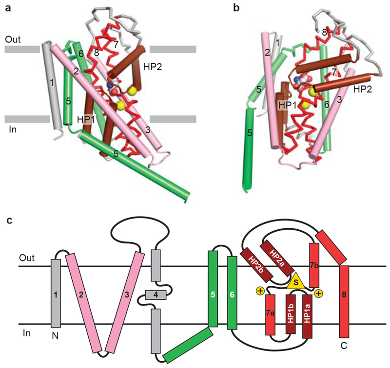
a, View of core transmembrane helices for GltPh illustrating how the first 6 transmembrane segments form a cradle harboring the elements of the transporter machinery. The functionally essential reentrant hairpin loops (HP1/HP2) are in brown, the partially unwound TM7 and the amphipathic TM8 are in red. View is parallel to the membrane and only one subunit of the GltPh trimer is shown. b, Same elements as panel (a) viewed approximately perpendicular to the membrane. The bound substrate (carbon, gray; oxygen, red; nitrogen, blue) and sodium ions (yellow) are shown in CPK representation. c, Topology diagram for GltPh with substrate and ions depicted as yellow triangle and circles, respectively.
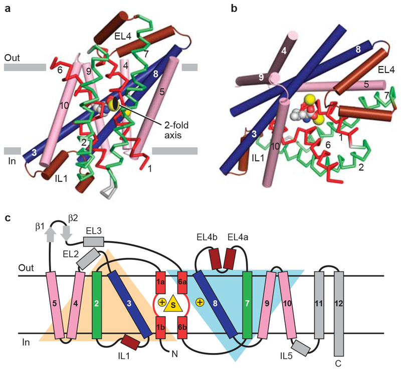
a, View of the core 5+5 repeat structure for LeuT showing the inverted scaffold of TMs 4/5 and 9/10 (pink) holding the long bracing helices (TMs3/8; blue) and the jointed, finger-like and partially unwound TM1/6 helices (red). Bracing TMs 1/6 are TMs 2/7 (green). Reentrant, pseudo 2-fold related loops that either partially (EL4) or fully (IL1) occluded central binding site are shown in brown. View is parallel to the membrane. b, Same elements as in panel (a) viewed approximately perpendicular to the membrane. The bound substrate (carbon, gray; oxygen, red; nitrogen, blue) and sodium ions (yellow) are shown in CPK representation. c, Topology diagram for LeuT with substrate and ions depicted as yellow triangle and circles, respectively..
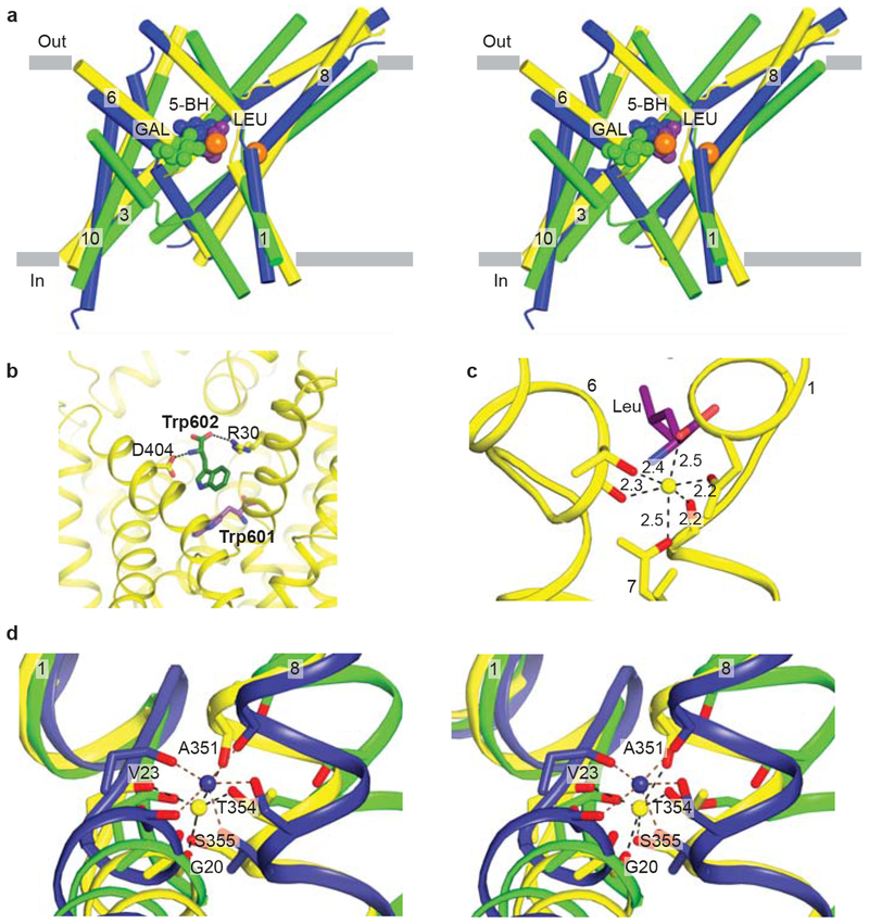
a, Stereo diagram of the superpositioned occluded structures of LeuT (yellow), Mhp1 (blue), and vSGLT (green) showing the location of their primary substrate binding sites roughly in the middle of the membrane bilayer and close to the discontinuous regions of TMs 1 and 6. Substrates and LeuT Na ions (orange) are shown in CPK representation. For clarity, only TMs 1, 3, 6, 8, and 10 are shown. b, View of the secondary binding site in LeuT. A second Trp molecule, Trp 602, is bound between R30 and D404 in the open-to-out conformation stabilized by Trp 601 in the primary binding site. c, Na1 ion in LeuT is octahedrally coordinationed by residues from TMs 1, 6, and 7 as well as bound leucine (purple). d, Stereo representation of superpositioned LeuT (yellow), vSGLT (green), and Mhp1 (blue) structures shows the location of their Na2 sites. Na2 of LeuT and Mhp1 are shown as yellow and blue spheres, respectively. Residues contributing side chain and main chain oxygens that coordinate Na2 are shown as sticks with LeuT residues labeled.
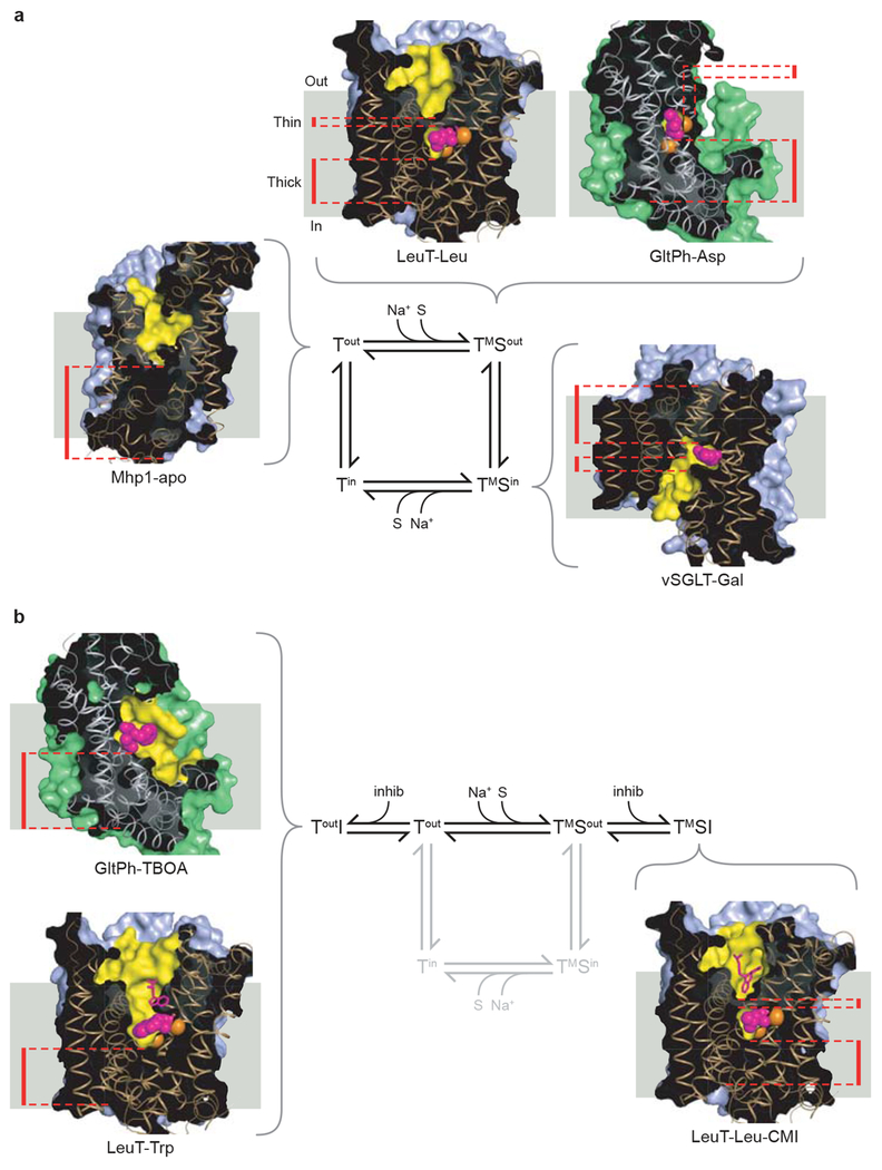
a, Transport cycle based upon an alternating access type mechanism together with insights from crystallographic studies. Known transporter structures that represent intermediate states are shown. Clockwise from the Tout state: Mhp1-apo (PDB 2JLN), LeuT-Leu (PDB 2A65), GltPh-Asp (PDB 2NWX), vSGLT-Gal (PDB 3DH4). b, The inhibitory branches of the transport cycle from panel a. On the left, structures of GltPh-TBOA (PDB 2NWW) and LeuT-Trp (PDB 3F3A) represent an open-to-out competitive-inhibitor bound state. On the right, the structure of LeuT-Leu-CMI (PDB 2Q6H) represents a non-competitive inhibitor-bound occluded state. Cross-sectional illustrations of the crystal structures of each transporter are shown associated with the states of the cycle that they represent. The positions of the ‘thin’ gates and ‘thick’ gates are highlighted by red dashed lines. The solvent-accessible surface area, calculated with a probe radius of 1.4 Å, is shown in light blue for the LeuT-fold structures or green for GltPh-fold structures. The yellow regions highlight the surfaces of the binding site and cavities that penetrate the structures. Bound ligands, shown as van der Waals spheres, are colored magenta, with sodium ions colored orange. The view of each transporter is approximately parallel to the membrane plane, with the extracellular side at the top of each figure.
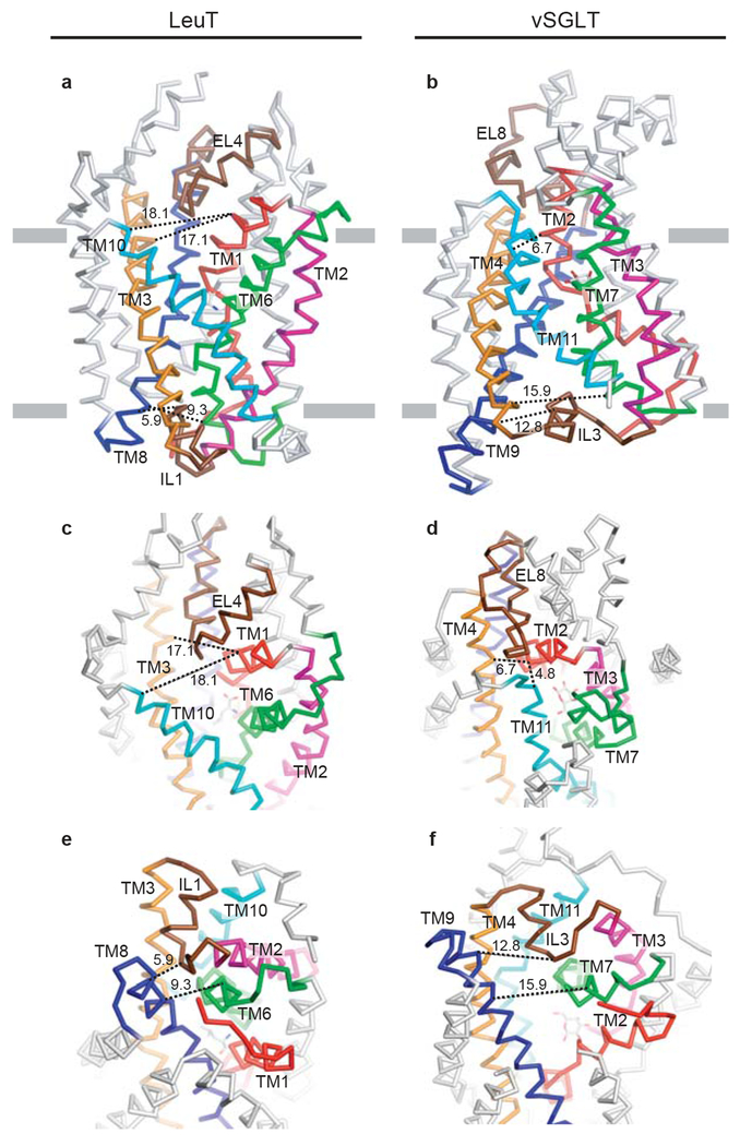
a, and b, show membrane-parallel views of LeuT and vSGLT. c, and d, show a top-down view of the extracellular pathway. e, and f, show a bottom-up view of the intracellular pathway. Equivalent structural elements are colored the same in both LeuT and vSGLT. To help gauge the re-organization of the extra- and intracellular elements, black dashed lines indicate distance measurements between structural elements, measured from structurally similar residues in the two transporters. Considering the internal two-fold symmetry, note the similar organization of the open LeuT extracellular pathway to the open vSGLT intracellular pathway, and the similarity of the closed vSGLT extracellular pathway to the closed LeuT intracellular pathway.
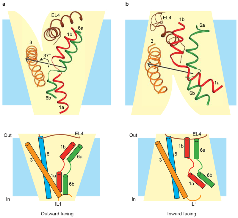
TMs 1 (red), 3 (orange), 6 (green), and 8 line the central translocation pathway with EL4 and IL1 acting as lids that seal the extracellular and intracellular gates, respectively, in their closed states. a, The outward-facing arrangement of central helices in substrate-bound LeuT. b, The inward-facing arrangement of central helices in substrate-bound vSGLT, with LeuT numbering for comparison with panel a. TM 8 and IL1 are omitted from the figure for clarity. TMs 1 and 6 rotate approximately 37 degrees relative to TMs 3 and 8 in transitioning from the outward-facing state adopted by LeuT in (a) to the inward-facing state adopted by vSGLT in (b). The rotation axis, shown in black, and the angle of rotation were calculated using DynDom. Cartoon representations of outward-facing and inward-facing states, adapted from Yamashita et al, are shown below the corresponding ribbon diagrams.
References
-
- Quick MW (ed.) Transmembrane Transporters (Wiley-Liss, Inc., Hoboken, NJ, 2002).
-
- Roux MJ & Supplisson S Neuronal and glial glycine transporters have different stoichiometries. Neuron 25, 373–383 (2000). - PubMed
-
- Chakrabarti AC & Deamer DW Permeability of lipid bilayers to amino acids and phosphate. Biochim. Biophys. Acta 1111, 171–177 (1992). - PubMed
-
- Supplisson S & Roux MJ Why glycine transporters have different stoichiometries. FEBS Lett. 529, 93–101 (2002). - PubMed
-
- Sobczak I & Lolkema JS Structural and mechanistic diversity of secondary transporters. Cur. Opin. Microbiol 8, 161–167 (2005). - PubMed
Publication types
MeSH terms
Substances
Grants and funding
LinkOut - more resources
Full Text Sources
Miscellaneous
