

Review
doi: 10.3174/ajnr.A1654.
Epub 2009 May 20.
Conebeam CT of the head and neck, part 2: clinical applications
Affiliations
- PMID: 19461061
- PMCID: PMC7051564
- DOI: 10.3174/ajnr.A1654
Item in Clipboard
Review
Conebeam CT of the head and neck, part 2: clinical applications
AJNR Am J Neuroradiol.
2009 Aug.
Abstract
Conebeam x-ray CT (CBCT) is being increasingly used for point-of-service head and neck and dentomaxillofacial imaging. This technique provides relatively high isotropic spatial resolution of osseous structures with a reduced radiation dose compared with conventional CT scans. In this second installment in a 2-part review, the clinical applications in the dentomaxillofacial and head and neck regions will be explored, with particular emphasis on diagnostic imaging of the sinuses, temporal bone, and craniofacial structures. Several controversies surrounding the emergence of CBCT technology will also be addressed.
Figures
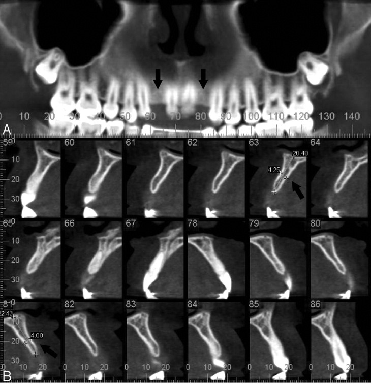
Noncontrast dentomaxillofacial CBCT scan (iCAT) of a patient with congenital absence of the maxillary lateral incisors (0.4-mm pixels, 120 kVp, 18.66 mA). A, Reconstructed panoramic view of the maxilla demonstrates bilateral lateral incisor absence (arrows). B, Sequential parasagittal/oblique views through the maxillary alveolar bone demonstrate planned implant locations (arrows).
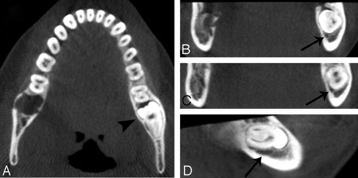
Noncontrast dentomaxillofacial CBCT scan (iCAT) of a patient with an impacted left mandibular third molar (0.4-mm pixels, 120 kVp, 18.66 mA). A, Axial view through the mandible demonstrates the impacted molar on the left side (arrowhead). B−D, Coronal (B and C) and sagittal (D) views through the mandibular body depict the proximity of the underlying mandibular canal (arrows) to the impacted molar.
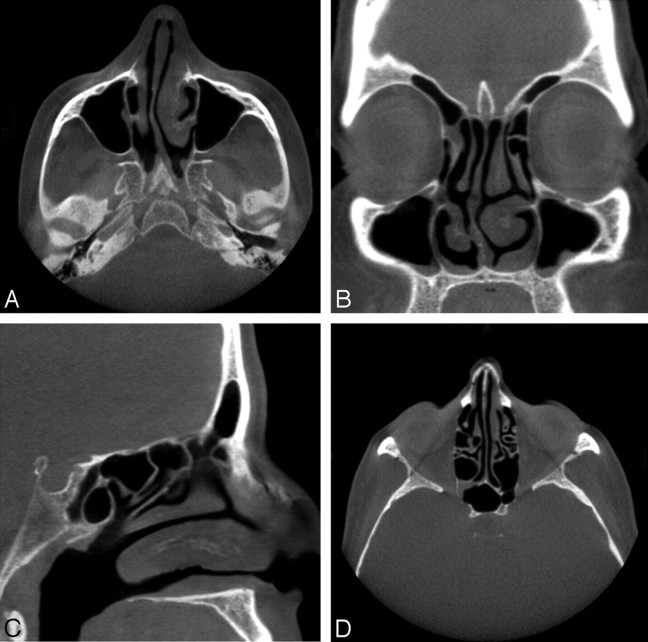
Noncontrast CBCT scan of a 56-year-old acquired with a sinus protocol (40 seconds, 600 frames, 0.4-mm pixels, 120 kVp, 48 mA). A, Axial section demonstrates right-sided deviation of the nasal septum and mucosal thickening in the left nasal cavity. B, Coronal section redemonstrates mucosal thickening of the left nasal cavity. C, Left paramedian sagittal section. D, Axial view of the ethmoid air cells and sphenoid sinus with mild opacification in the region of the right sphenoethmoidal recess.
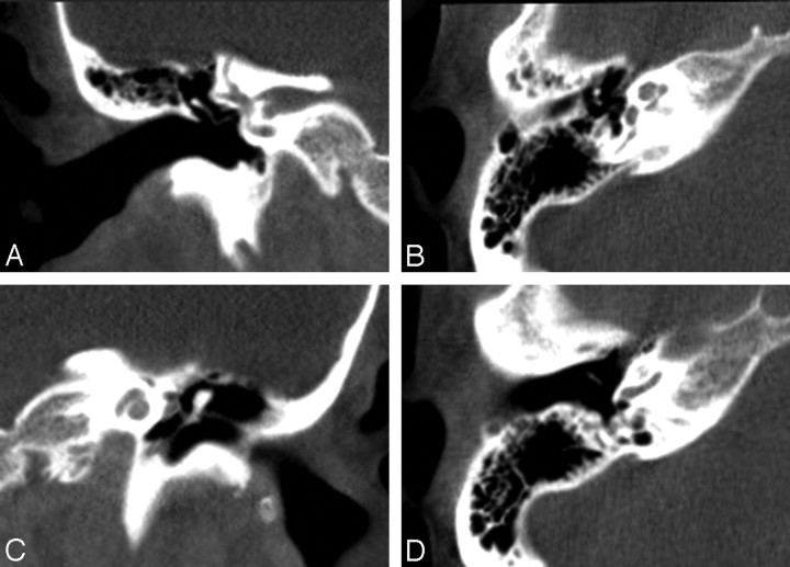
Noncontrast CBCT scan of a 50-year-old acquired with a temporal bone protocol (40 seconds, 600 frames, 0.3-mm-pixels, 125 kVp, 50.85 mA). A, Coronal image of the normal right temporal bone demonstrates the vestibulocochlear nerve, body and long limb of the incus, as well as the stapedial neck and crura in the fossa of the oval window. B, Axial section at the level of the right mesotympanum demonstrates the head of the malleus, short limb of the incus, and stapedial crura, as well as the cochlear nerve, tensor tympani, and mastoid part of the facial nerve VII. C, Coronal section through the left cochlea demonstrates the modiolus, tympanic part of facial nerve VII, tensor tympani, and malleus. D, Axial section through the right mesotympanum at the level of the round window demonstrates the handle of the malleus, base of cochlea, and mastoid portion of the facial nerve VII.
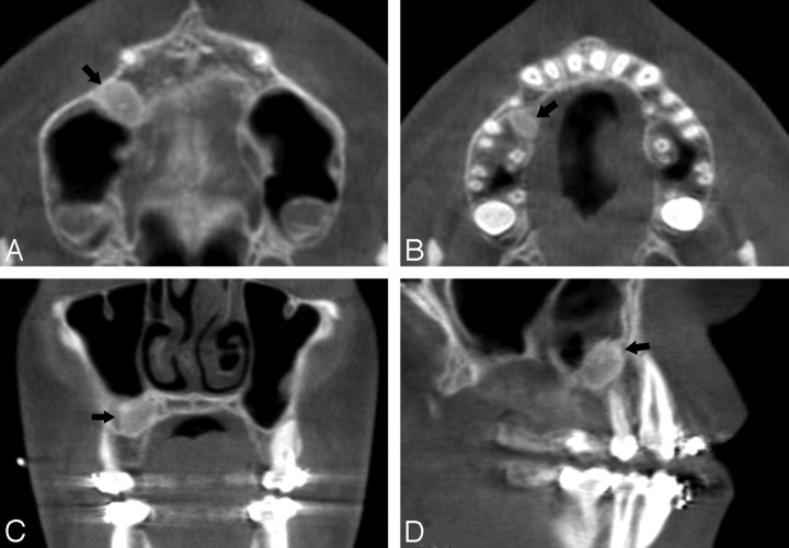
Noncontrast CBCT scan of a 13-year-old boy acquired with a sinus protocol (40 seconds, 600 frames, 0.4-mm pixels, 120 kVp, 48 mA). A, Axial section at the level of the maxillary sinus floor demonstrates a 1.0 × 0.7 × 1.0-cm oval mass in the alveolar process of the right maxilla (arrow). B, Axial image highlights the inferior extent of the lesion in A. C and D, Coronal and sagittal images, respectively, of the lesion in A.
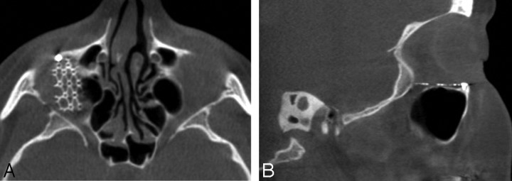
Noncontrast CBCT scan of a 45-year-old (40 seconds, 600 frames, 0.4-mm pixels, 120 kVp, 48 mA) obtained after repair of a right orbital floor fracture. A, Axial image demonstrates a metal fixture implanted over the right orbital floor. B, Metallic implant is seen in the sagittal section.
References
-
- Robb RA. The dynamic spatial reconstructor: an x-ray video-fluoroscopic CT scanner for dynamic volume imaging of moving organs. IEEE Trans Med Imaging 1982;1:22–33 - PubMed
-
- Saint-Félix D, Trousset Y, Picard C, et al. In vivo evaluation of a new system for 3D computerized angiography. Phys Med Biol 1994;39:583–95 - PubMed
-
- Silver MD, Yahata M, Saito Y, et al. Volume CT of anthropomorphic phantoms using a radiation therapy simulator. In: Shaw R, ed. Medical Imaging VI: Instrumentation: Proceedings of SPIE 1992;1651:197–211
-
- Cho PS, Johnson RH, Griffin TW. Cone-beam CT for radiotherapy applications. Phys Med Biol 1995. :40:1863–83 - PubMed
Publication types
MeSH terms
LinkOut - more resources
Full Text Sources
Other Literature Sources