Review
. 2009 Jun;136(12):1963-75.
doi: 10.1242/dev.022426.

Selective plane illumination microscopy techniques in developmental biology

Affiliations
Review

Selective plane illumination microscopy techniques in developmental biology

Jan Huisken et al. Development. 2009 Jun.

Abstract

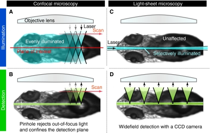
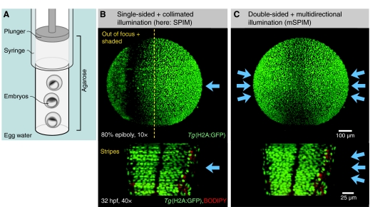
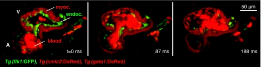
Selective plane illumination microscopy (SPIM) and other fluorescence microscopy techniques in which a focused sheet of light serves to illuminate the sample have become increasingly popular in developmental studies. Fluorescence light-sheet microscopy bridges the gap in image quality between fluorescence stereomicroscopy and high-resolution imaging of fixed tissue sections. In addition, high depth penetration, low bleaching and high acquisition speeds make light-sheet microscopy ideally suited for extended time-lapse experiments in live embryos. This review compares the benefits and challenges of light-sheet microscopy with established fluorescence microscopy techniques such as confocal microscopy and discusses the different implementations and applications of this easily adaptable technology.


Figures

Fig. 1.
Fig. 1.
The concept behind fluorescence light-sheet microscopy. In light-sheet microscopy, fluorescence excitation (blue arrow) and detection (green arrow) are split into two distinct optical paths. The illumination axis is orthogonal to the detection axis. A microscope objective lens and common widefield optics are used to image the sample onto a camera (not shown). The illumination optics are designed to illuminate a very thin volume around the focal plane of the detection objective. Many different implementations of this principle exist, however, the most common one is the generation of a sheet of laser light that illuminates the sample in the focal plane from one side.
Fig. 2.
Fig. 2.
Advantages of light-sheet microscopy compared with confocal microscopy. Light-sheet microscopy features faster acquisition and less photo-bleaching than confocal microscopy. To illustrate the difference between laser scanning confocal microscopy (LSCM; A,B) and light-sheet microscopy (C,D), the processes of illumination (A,C) and detection (B,D) are split. (A,B) In LSCM, a tightly focused laser beam is scanned across the sample (A), thereby exposing the sample to high-intensity light not only in the plane of interest, but also above and below. (B) A pinhole rejects much of the excited fluorescence and confines the image to the plane of interest. (C,D) In light-sheet microscopy, a light-sheet from the side (C), which overlaps with the plane of interest, illuminates the sample in a thin slice. Photo-bleaching is thereby considerably reduced. (D) All the fluorescence is collected and imaged onto a CCD camera. Such widefield detection is fast and benefits from modern CCD technology.
Fig. 3.
Fig. 3.
Typical SPIM components (not to scale). A typical SPIM setup consists of an illumination, a detection and (optionally) a photo-manipulation unit. (A) Fluorescence illumination: the light from one or more lasers is collected and focused by optics to become a sheet of light in the focal plane of the detection lens. An acousto-optic tunable filter (AOTF) is used to precisely control the exposure of the sample. (B) Transmission light: a red light emitting diode (LED) array provides uniform transmission light without bleaching the sample. (C) Fluorescence detection: the fluorescence from the sample is imaged onto one or more cameras. As shown here, two cameras are used to simultaneously image green and red fluorescence split by a dichroic mirror. The magnification of the system is given by the objective, the camera adapters and the optional magnification changer. (D) Photo-manipulation: laser light, which can be used to selectively photo-bleach, photo-convert or microdissect, is directed through the detection lens and focused onto the sample. Either the beam or the sample is moved to irradiate multiple points or areas in the sample.
Fig. 4.
Fig. 4.
A comparison of light-sheet microscopy techniques. (A) In epifluorescence microscopy, a single objective lens (obj) is used to both illuminate the sample (s) and to collect its fluorescence along the same path. The sample is usually prepared on a glass slide or in a dish. (B-G) In light-sheet-based imaging techniques, by contrast, the sample is illuminated from the side by one or two additional beam paths (B-E), through (F) or along (G) the detection lens. (B) In selective plane illumination microscopy (SPIM), the detection lens is horizontally aligned and immersed into a fluid-filled chamber (ch). The sample is embedded in a transparent gel, immersed in the medium and held from the top. A single cylindrical lens (cyl) is used to form the light-sheet inside the chamber. A stack of images is acquired by moving the sample in a stepwise fashion along the detection axis. Optionally, the sample is turned for complementary data acquisition. (C) In objective-coupled planar illumination microscopy (OCPI), the illumination light is delivered through a fiber and focused by optics that are directly attached to the detection lens. A three-dimensional (3D) image stack is rapidly acquired by moving this arrangement, leaving the sample at rest. (D) Ultramicroscopy was developed to image fixed and cleared samples enclosed in a chamber. Two counter-propagating laser beams are focused into a light-sheet by cylindrical lenses and illuminate the sample simultaneously from both sides, thereby providing a more even illumination in clear tissue. (E) In multidirectional SPIM (mSPIM), the sample is illuminated independently from two sides over a range of angles. Shadowing and scattering (a common problem in live, scattering tissue) are thereby reduced. Three water-dipping objective lenses eliminate the need for any chamber windows. (F) In highly inclined and laminated optical sheet (HILO) microscopy, a single lens is used for both illumination and detection; however, the light-sheet is tilted and intersects the focal plane only in the center of the field of view. (G) The concept of an attachment ring to provide light-sheet illumination could be implemented as an add-on to existing microscopes. Blue arrows indicate the direction of illumination, green arrows indicate the direction of detection.
Fig. 5.
Fig. 5.
Comparison of single-sided SPIM and mSPIM. Multidirectional selective plane illumination microscopy (mSPIM) dramatically reduces absorption and scattering artifacts and provides an evenly illuminated focal plane, as demonstrated with zebrafish embryos. Blue arrows indicate direction of illumination. (A) Schematic representation of the sample preparation for light-sheet microscopy: multiple zebrafish embryos are embedded in a low melting point agarose cylinder inside a syringe. To image the embryos, the cylinder is partially pushed out of the syringe and dips into the medium-filled chamber (not shown). Three embryos are stacked in the agarose and are sequentially imaged during a time-lapse recording. Shown are early embryos embedded and imaged in their chorion. (B) 8 hpf (top) and 32 hpf (bottom) zebrafish embryos imaged using SPIM. The illumination from the right in SPIM does not penetrate the whole embryo at 80% epiboly. The light-sheet gets refracted and renders the left half blurry and patchy. (B, bottom) Stripes are especially apparent at later stages, when pigmentation has occurred, which can block the light-sheet. (C) In mSPIM, by contrast, the sample is sequentially illuminated from two sides from a range of angles. The double-sided illumination yields almost even illumination in the early embryo (C, top), and the pivoting light-sheet eliminates most of the stripes and shadows in the late embryo (C, bottom). See Movie 1 in the supplementary material.
Fig. 6.
Fig. 6.
Vascular endothelial cell dynamics at long and short time scales. Dynamics in cell migration are captured with high-speed SPIM time-lapse recordings. (A) Individual or multiple zebrafish larvae are embedded in low melting point agarose. Shown is a single zebrafish larva (Fry) in a vertical orientation, which is ideal for imaging the organs in the trunk and the vasculature in the tail. (B-B″) Individual frames from a time-lapse sequence monitoring the sprouting of a vessel (arrow) in the head of a 24 hpf zebrafish. Tg(flk1:GFP)s843 expression labels the endothelial cells and Tg(gata1:DsRed)sd2 expression labels the red blood cells. Shown are maximum intensity projections of a 3D stack. (C-C″) Highly dynamic protrusions (arrowheads) in vascular endothelial cells labeled by Tg(flk1:ras-mCherry)s896 expression in a 32 hpf zebrafish. A 3D stack was acquired every minute. Shown are maximum intensity projections captured 10 minutes apart. See Movies 2 and 3 in the supplementary material.
Fig. 7.
Fig. 7.
High-speed recordings of zebrafish heart beats. High-speed mSPIM video sequence of a transgenic fish expressing fluorescent proteins in the endocardium [Tg(flk1:GFP)s843], myocardium [Tg(cmlc2:DsRed)s879] and blood [Tg(gata1:DsRed)sd2]. The movie was recorded at 69 frames per second. Three frames are shown, corresponding to the atrial diastole (left), the atrial systole (middle) and the ventricular diastole (right). A, atrium; V, ventricle; myoc., myocardium; endoc., endocardium. See Movie 4 in the supplementary material.
Fig. 8.
Fig. 8.
Dendrite pruning in class IV da neurons in Drosophila. Drosophila pupae can be imaged in SPIM over many hours using the depicted embedding. (A) A Drosophila pupa is partially inserted into a glass capillary and embedded in agarose. The high refractive index medium facilitates imaging structures inside the pupal case, while the glass capillary provides enough air for the pupa to survive and space to hatch. (B) Schematic of the abdomen of an early Drosophila pupa, showing the position and the dendritic fields of dorsal class IV da (ddaC) neurons. (C-G) Dendrite pruning of one ddaC neuron (outlined in B) during the course of almost 10 hours; shown are timepoints between 3 hours and 20 minutes and 11 hours and 40 minutes after pupal formation. Arrowheads point to detaching and degenerating dendrites. Only the axon (arrow) remains in G. See Movie 5 in the supplementary material.

Similar articles

Cited by

References

    1. Arnaout, R., Ferrer, T., Huisken, J., Spitzer, K., Stainier, D. Y. R., Tristani-Firouzi, M. and Chi, N. C. (2007). Zebrafish model for human long QT syndrome. Proc. Natl. Acad. Sci. USA 104, 11316-11321. - PMC - PubMed
    1. Becker, K., Jährling, N., Kramer, E. R., Schnorrer, F. and Dodt, H.-U. (2008). Ultramicroscopy: 3D reconstruction of large microscopical specimens. J. Biophotonics 1, 36-42. - PubMed
    1. Breuninger, T., Greger, K. and Stelzer, E. H. K. (2007). Lateral modulation boosts image quality in single plane illumination fluorescence microscopy. Opt. Lett. 32, 1938-1940. - PubMed
    1. Buytaert, J. A. N. and Dirckx, J. J. J. (2007). Design and quantitative resolution measurements of an optical virtual sectioning three-dimensional imaging technique for biomedical specimens, featuring two-micrometer slicing resolution. J. Biomed. Opt. 12, 014039. - PubMed
    1. Denk, W. and Horstmann, H. (2004). Serial block-face scanning electron microscopy to reconstruct three-dimensional tissue nanostructure. PLoS Biol. 2, e329. - PMC - PubMed

Publication types

MeSH terms

LinkOut - more resources