. 2009 Oct;62(4):943-54.
doi: 10.1002/mrm.22082.

Prospective real-time correction for arbitrary head motion using active markers

Affiliations

Prospective real-time correction for arbitrary head motion using active markers

Melvyn B Ooi et al. Magn Reson Med. 2009 Oct.

Abstract

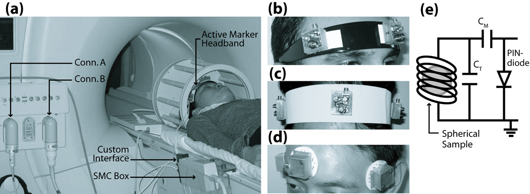
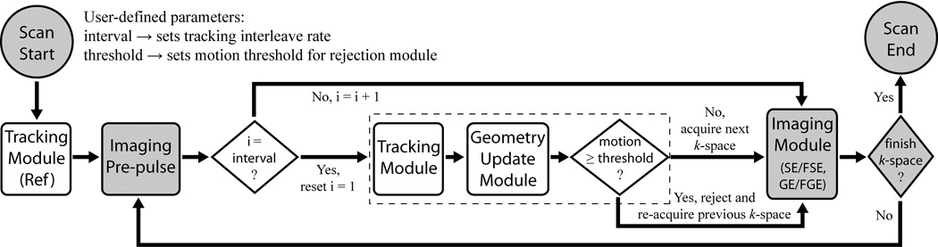
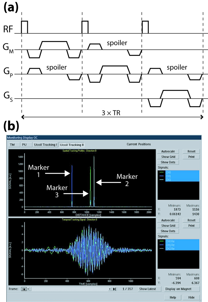
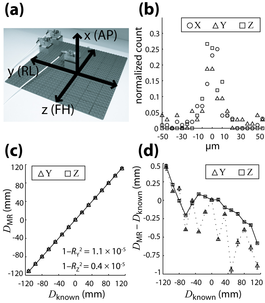
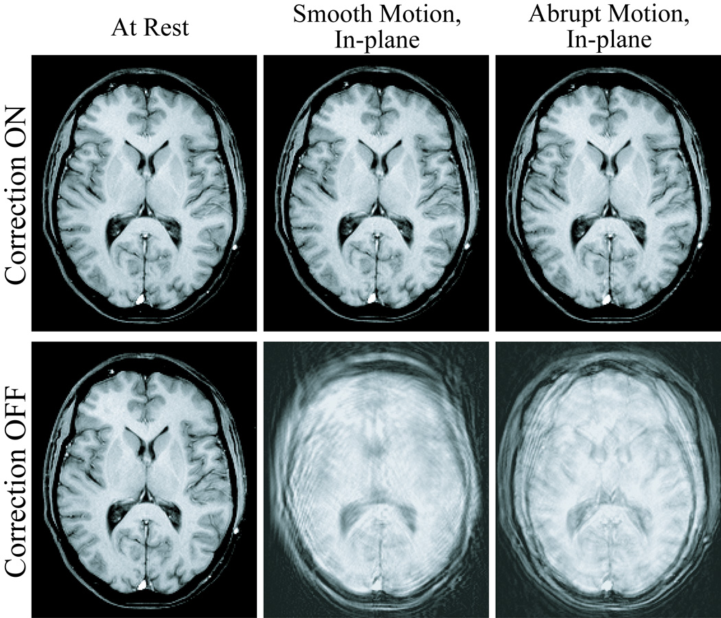
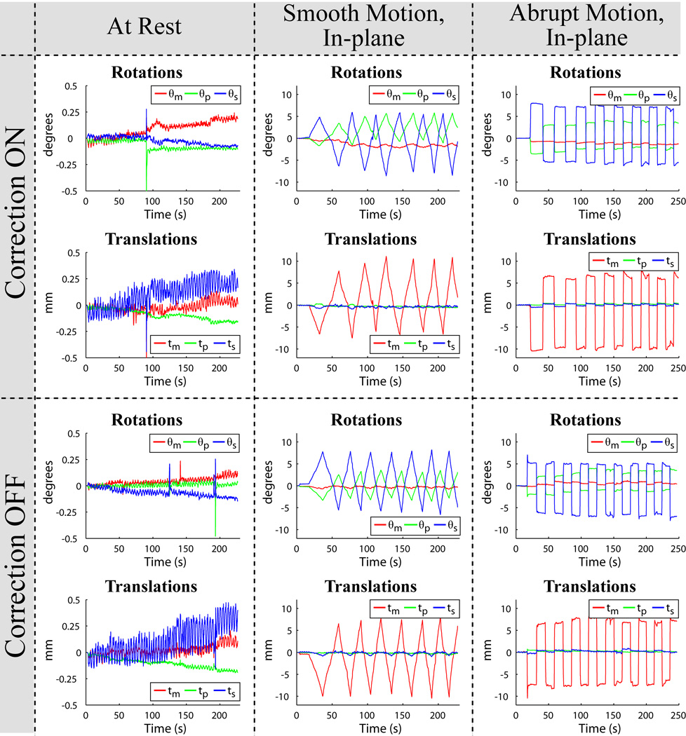
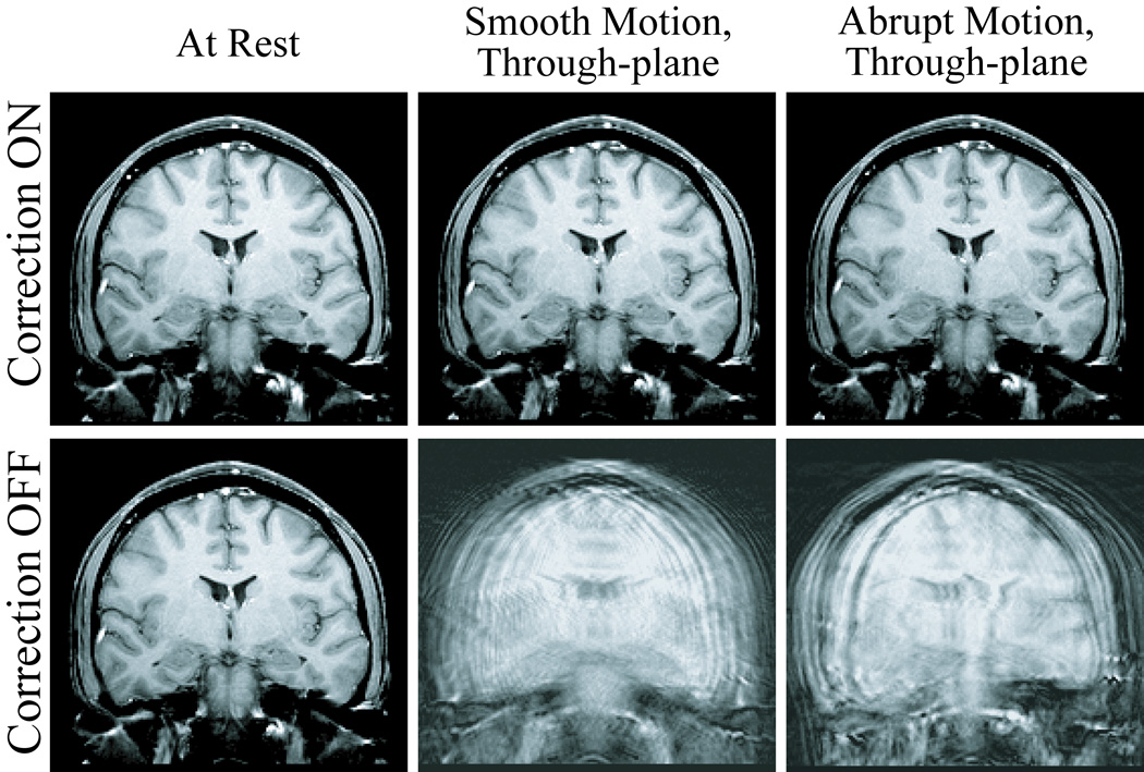
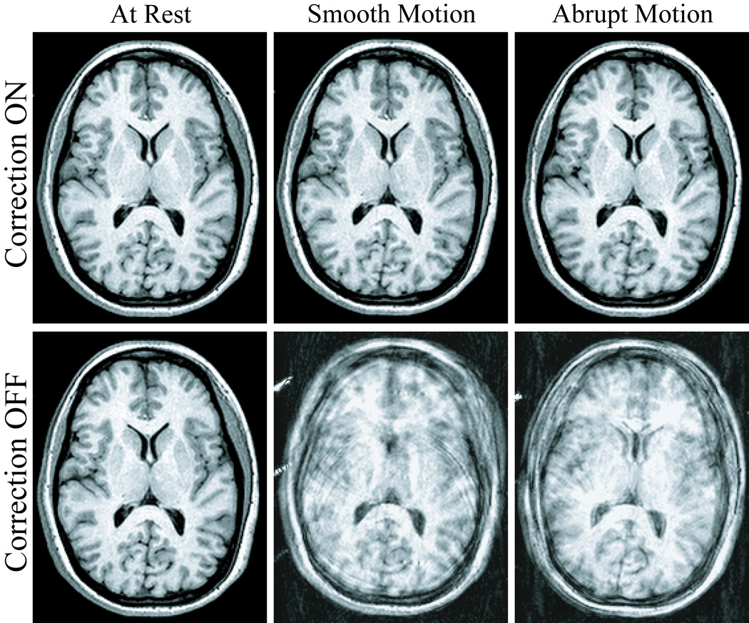
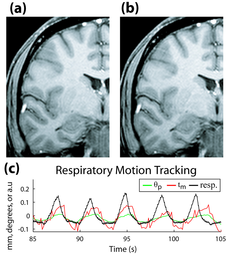
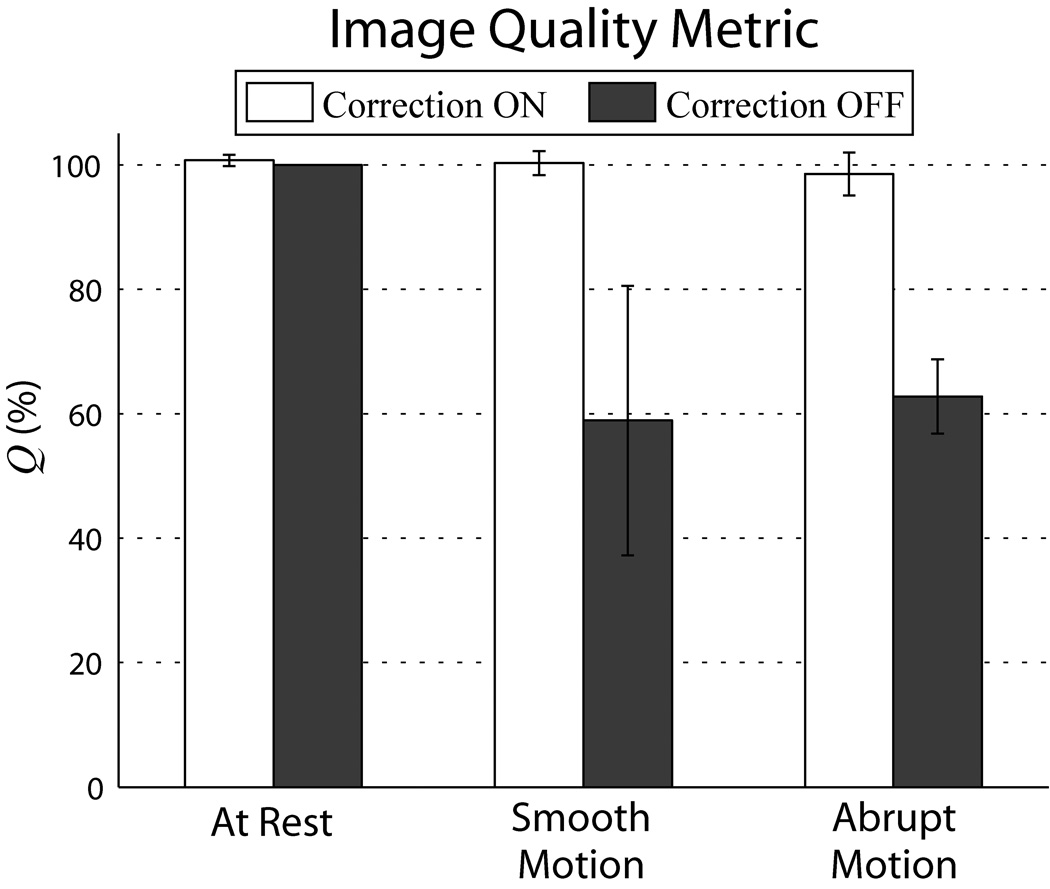
Patient motion during an MRI exam can result in major degradation of image quality, and is of increasing concern due to the aging population and its associated diseases. This work presents a general strategy for real-time, intraimage compensation of rigid-body motion that is compatible with multiple imaging sequences. Image quality improvements are established for structural brain MRI acquired during volunteer motion. A headband integrated with three active markers is secured to the forehead. Prospective correction is achieved by interleaving a rapid track-and-update module into the imaging sequence. For every repetition of this module, a short tracking pulse-sequence remeasures the marker positions; during head motion, the rigid-body transformation that realigns the markers to their initial positions is fed back to adaptively update the image-plane-maintaining it at a fixed orientation relative to the head-before the next imaging segment of k-space is acquired. In cases of extreme motion, corrupted lines of k-space are rejected and reacquired with the updated geometry. High-precision tracking measurements (0.01 mm) and corrections are accomplished in a temporal resolution (37 ms) suitable for real-time application. The correction package requires minimal additional hardware and is fully integrated into the standard user interface, promoting transferability to clinical practice.


Figures

Fig. 1
Fig. 1
(a) Hardware setup for motion correction package. Multi-channel MR system allows dual-coil option for imaging using a standard bird-cage coil (Conn. A), and tracking using the active marker headband (Conn. B). Active markers communicate with MR system via SMC circuitry, which is mounted to the side of the scanner bed. (b–d) Prototype headband designs include hairband, velcro-strap, and electrode-style. Design (b) was used for all in vivo results presented. (e) Active marker schematic, consisting of a micro-coil wrapped around a spherical sample, with appropriate tuning and matching capacitance. Resonant circuit is actively detuned during RF-transmit via PIN-diode and SMC-controlled decoupling current.
Fig. 2
Fig. 2
Flowchart of motion tracking and prospective correction strategy – consisting of tracking, geometry update, and rejection modules (white boxes) – interleaved into a generic imaging pulse-sequence (shaded boxes). The algorithm’s primary functionality is enclosed by the dashed boundary.
Fig. 3
Fig. 3
(a) Basic tracking pulse-sequence using only positive readout gradients (time = 3×TR). For B0-correction, this sequence is repeated with reversed polarities for each readout (time = 6×TR); positions are then determined by averaging the independently computed locations from the two opposite readouts. (b) Scanner GUI monitoring of tracking profiles in space (upper plot) and time (lower plot) of three active markers after the first projection readout GM. Similar plots are displayed in real-time for all three gradient directions over the scan’s duration.
Fig. 4
Fig. 4
(a) Setup of grid for validation tests showing its orientation relative to gradient and patient axes. (b) Reproducibility of MR position measurements along the x,y,z gradient axes, illustrated as a histogram distribution of the deviation of each measurement from its corresponding mean. (c) Accuracy of measurements is displayed by comparing MR and caliper (known) measured distances along the y and z axes. Least-squares linear regression fits result in high correlation coefficients RY and RZ for both directions. (d) Measurement error between MR and caliper values as a function of distance. Error bars in (c,d) are the standard deviations of MR measurements at each position, reflecting the high reproducibility in (b). All curves are plotted with B0-corrected data; plots using positive readout gradients are similar in nature.
Fig. 5
Fig. 5
Six different 2D-GE axial scans, demonstrating improvements in image quality for the in-plane motion case. The volunteer is at rest (first column), and performing smooth (second column) and abrupt (third column) deliberate left-right head-shakes; two scans were acquired for each motion, with prospective correction turned ON (first row) and OFF (second row). The movements were well reproduced by the volunteer within each pair of acquisitions, as demonstrated by the corresponding tracking plots in Fig. 6.
Fig. 6
Fig. 6
Active marker motion tracking information for the six scans in Fig. 5, plotted as measured rotations (θm, θp, θs) and translations (tm, tp, ts) vs. time. For ease of reference, the layout of the plots above is identical to the layout of the images they correspond to in Fig. 5. The nature of the smooth-continuous (second column) and abrupt-intermittent (third column) head-shakes is apparent, and well reproduced by the volunteer during prospective correction ON (first row) and OFF (second row) acquisitions. The time axis covers the full scan duration, showing that motion occurred throughout the entire multi-slice acquisition.
Fig. 7
Fig. 7
Six different 2D-GE coronal scans, illustrating improvements in image quality for the through-plane motion case. The volunteer is at rest (first column), and performing smooth (second column) and abrupt (third column) deliberate left-right head-shakes, similar to those shown in Fig. 6; two scans were acquired for each motion, with prospective correction turned ON (first row) and OFF (second row).
Fig. 8
Fig. 8
Six different 3D-MPRAGE scans, demonstrating the flexibility of the prospective correction strategy in more complex imaging sequences. The volunteer is at rest (first column), and performing smooth (second column) and abrupt (third column) deliberate left-right head-shakes throughout the entire volumetric acquisition; two scans were acquired for each motion, with correction ON (first row) and OFF (second row).
Fig. 9
Fig. 9
(a) 2D-GE coronal image of volunteer at rest with correction ON, and (b) correction OFF. (c) Motion during the scan, measured with active markers (θp in degrees, tm in mm), and respiratory bellows sensor (arbitrary units), illustrating correlation between frequency of motion tracked by markers and respiratory cycle of volunteer.
Fig. 10
Fig. 10
Comparison of image quality between corrected vs. uncorrected scans using metric Q. For each of the three motions tested, each column represents the average Q over the three volunteer cases, while the error bars are standard deviations between cases. Substantial improvement in Q between corrected and uncorrected scans can be seen for both types of deliberate motions. Q’s were generated using ωc = 0.04 cycles/mm, sensitive to spatial variations < 12 mm. Similar results were found for the range of ωc tested. Note that changes in Q reflect relative changes in the high frequency power band, rather than total volume power.

References

    1. Righini A, de Divitiis O, Prinster A, Spagnoli D, Appollonio I, Bello L, Scifo P, Tomei G, Villani R, Fazio F, Leonardi M. Functional MRI: primary motor cortex localization in patients with brain tumors. Journal of Computer Assisted Tomography. 1996;20(5):702–708. - PubMed
    1. Ardekani BA, Bachman AH, Helpern JA. A quantitative comparison of motion detection algorithms in fMRI. Magnetic Resonance Imaging. 2001;19(7):959–963. - PubMed
    1. Thesen S, Heid O, Mueller E, Schad LR. Prospective acquisition correction for head motion with image-based tracking for real-time fMRI. Magnetic Resonance in Medicine. 2000;44(3):457–465. - PubMed
    1. Ehman RL, Felmlee JP. Adaptive technique for high-definition MR imaging of moving structures. Radiology. 1989;173(1):255–263. - PubMed
    1. Welch EB, Manduca A, Grimm RC, Ward HA, Jack CR., Jr Spherical navigator echoes for full 3D rigid body motion measurement in MRI. Magnetic Resonance in Medicine. 2002;47(1):32–41. - PubMed

Publication types