. 2009 Nov;72(2):244-51.
doi: 10.1016/j.ejrad.2009.05.054. Epub 2009 Jul 18.

Chest tomosynthesis: technical principles and clinical update

Affiliations

Chest tomosynthesis: technical principles and clinical update

James T Dobbins 3rd et al. Eur J Radiol. 2009 Nov.

Abstract

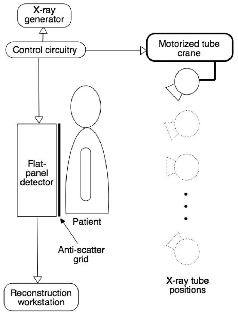
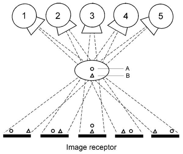
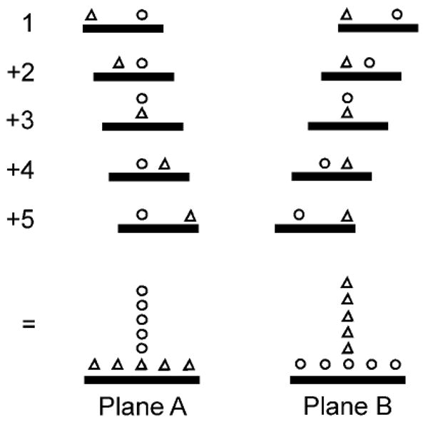
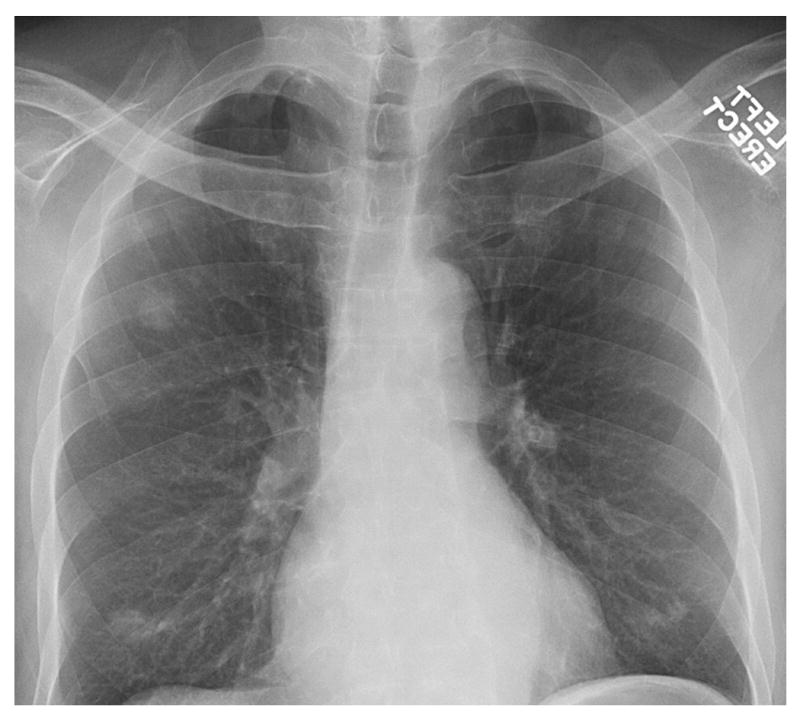
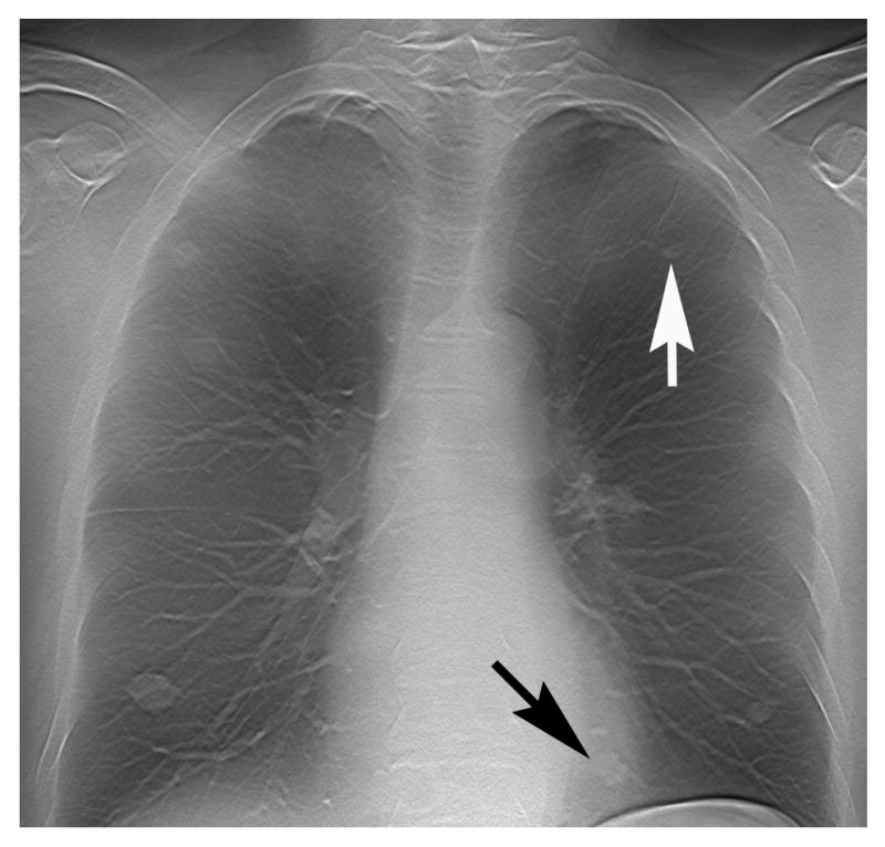
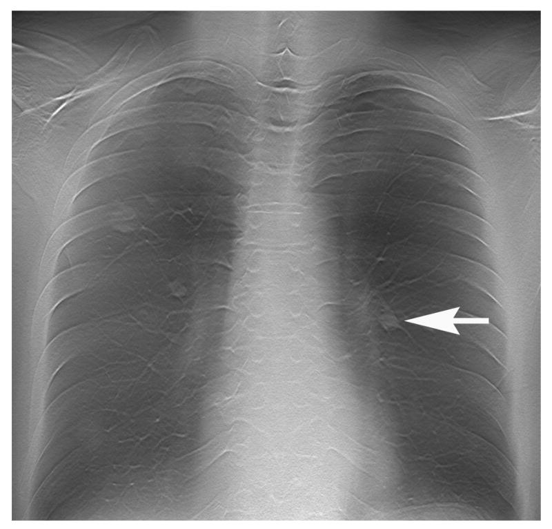
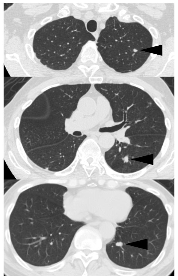
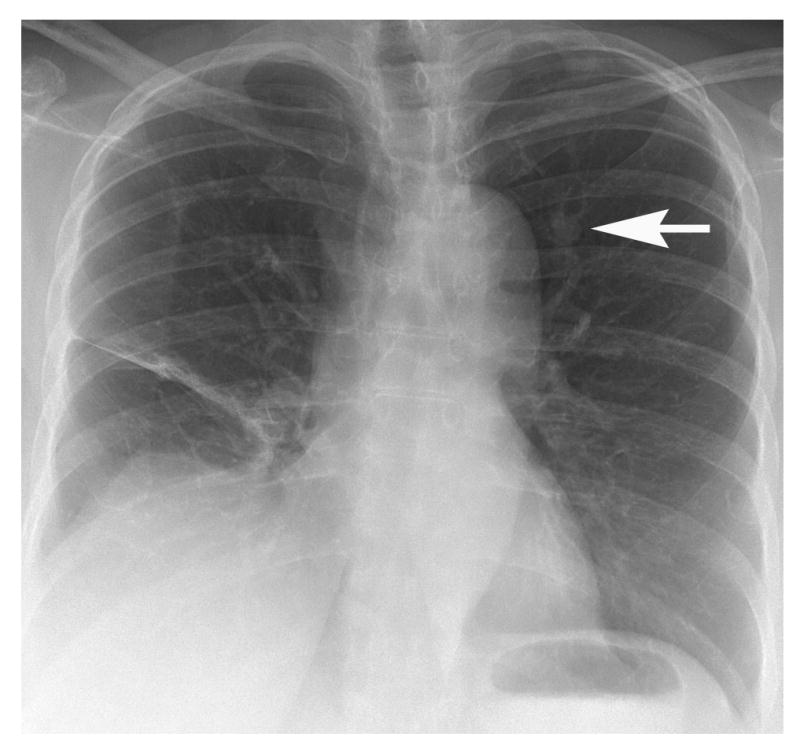
Digital tomosynthesis is a radiographic technique that can produce an arbitrary number of section images of a patient from a single pass of the X-ray tube. It utilizes a conventional X-ray tube, a flat-panel detector, a computer-controlled tube mover, and special reconstruction algorithms to produce section images. While it does not have the depth resolution of computed tomography (CT), tomosynthesis provides some of the tomographic benefits of CT but at lower cost and radiation dose than CT. Compared to conventional chest radiography, chest tomosynthesis results in improved visibility of normal structures such as vessels, airway and spine. By reducing visual clutter from overlying normal anatomy, it also enhances detection of small lung nodules. This review article outlines the components of a tomosynthesis system, discusses results regarding improved lung nodule detection from the recent literature, and presents examples of nodule detection from a clinical trial in human subjects. Possible implementation strategies for use in clinical chest imaging are discussed.


Figures

Figure 1
Figure 1. Basic components of a chest tomosynthesis device
A computer-controlled motorized tube crane moves the x-ray tube to a series of positions along a vertical path, acquiring a projection image on a flat-panel detector at each position. Control circuitry coordinates the tube mover, digital detector, and x-ray generator. A workstation produces the tomosynthesis reconstructed images.
Figure 2
Figure 2. Shift-and-add technique for tomosynthesis image reconstruction (reprinted from (6), by permission)
A. In this example, an x-ray tube moves to five discrete positions. Objects in Plane A and Plane B are projected at different locations in each image due to parallax. B. The five projection images are shifted and added together to yield a composite image with either the objects in Plane A or Plane B in sharp focus, depending on the magnitude of the shift.
Figure 3
Figure 3. Pulmonary metastases
A. Posteroanterior chest radiograph shows bilateral pulmonary nodules. B. Chest tomosynthesis image reconstructed through the mid-chest shows at least two nodules (arrows) not seen on PA radiograph (A). Note excellent depiction of vasculature, airway and ribs. C. Chest tomosynthesis image reconstructed through the posterior chest shows additional nodule (arrow) superimposed over left hilum on PA radiograph (A). D. CT (lung window) images confirm three nodules (arrowheads) seen on tomosynthesis images (B, C), but not clearly depicted on PA radiograph (A).
Figure 4
Figure 4. Pulmonary metastases
A. Posteroanterior chest radiograph shows findings of prior partial right lung resection for metastectomy and one left upper lobe nodule (arrow). B. Chest tomosynthesis image reconstructed through the mid-chest shows at least one nodule (black arrow) not seen on PA radiograph (A). Note left upper lobe nodule (white arrow). C. Chest tomosynthesis image reconstructed through the posterior chest shows an additional left lower lobe nodule (arrow) not seen on PA radiograph (A). D. CT (lung window) images confirm two nodules (arrowheads, bottom two panels) seen on tomosynthesis images (B, C), but not clearly depicted on PA radiograph (A). Note left upper lobe nodule (arrowhead, top panel) seen on both PA (A) and tomosynthesis images (B).

Similar articles

Cited by

References

    1. McAdams HP, Samei E, Dobbins J, 3rd, Tourassi GD, Ravin CE. Recent advances in chest radiography. Radiology. 2006;241:663–683. - PubMed
    1. Pascoal A, Lawinski CP, Mackenzie A, Tabakov S, Lewis CA. Chest radiography: a comparison of image quality and effective dose using four digital systems. Radiat Prot Dosimetry. 2005;114:273–277. - PubMed
    1. Ricke J, Fischbach F, Freund T, et al. Clinical results of CsI-detector-based dual-exposure dual energy in chest radiography. European Radiology. 2003;13:2577–2582. - PubMed
    1. MacMahon H, Li F, Engelmann R, Roberts R, Armato S. Dual energy subtraction and temporal subtraction chest radiography. J Thorac Imaging. 2008;23:77–85. - PubMed
    1. Dobbins JT, III, McAdams HP, Song JW, et al. Digital tomosynthesis of the chest for lung nodule detection: interim sensitivity results form an ongoing NIH-sponsored trial. Medical Physics. 2008;35:2554–2557. - PMC - PubMed

Publication types

MeSH terms