Review
. 2009 Sep 2;28(17):2511-31.
doi: 10.1038/emboj.2009.173. Epub 2009 Jul 23.

The life and miracles of kinetochores

Affiliations
Review

The life and miracles of kinetochores

Stefano Santaguida et al. EMBO J. .

Abstract

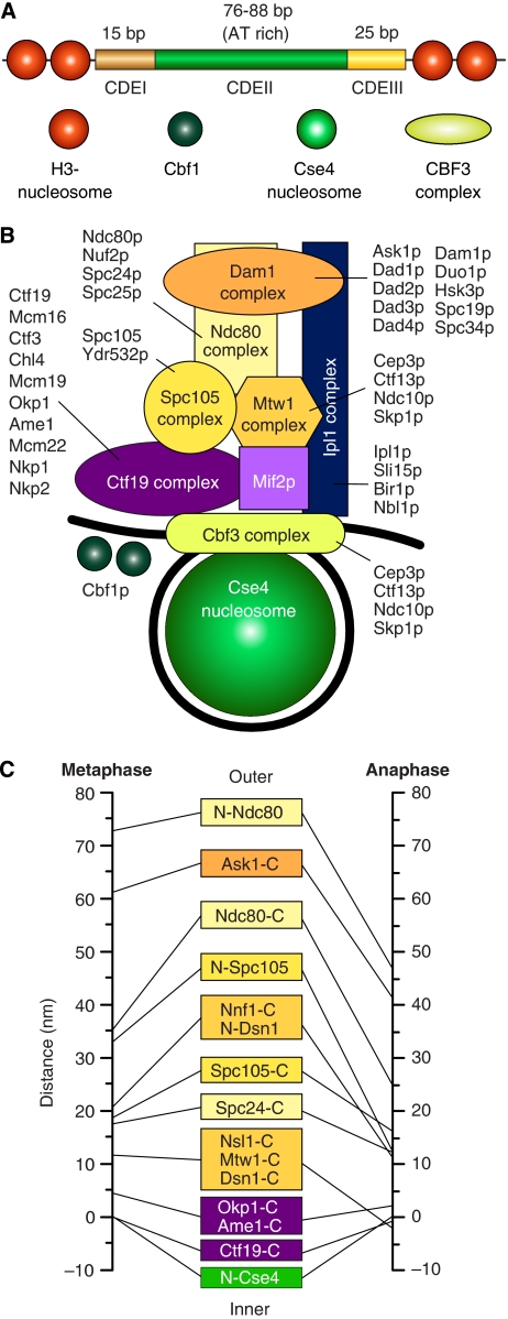
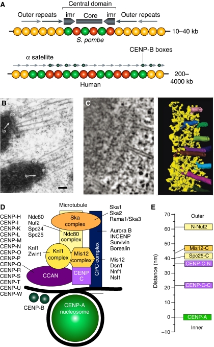
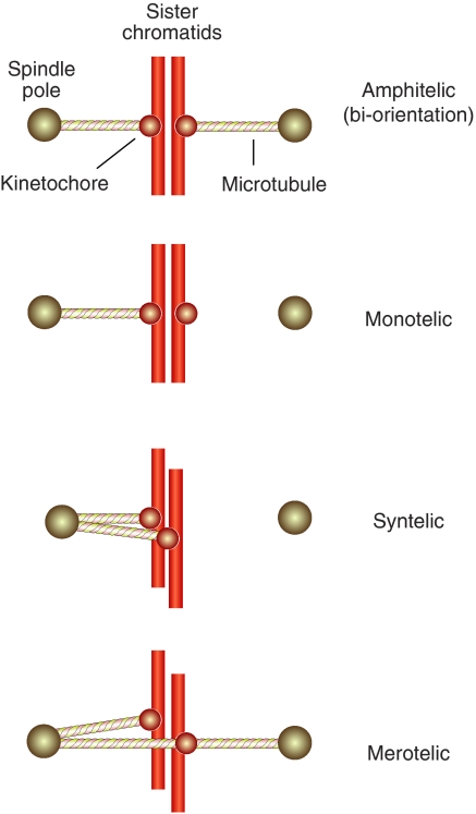
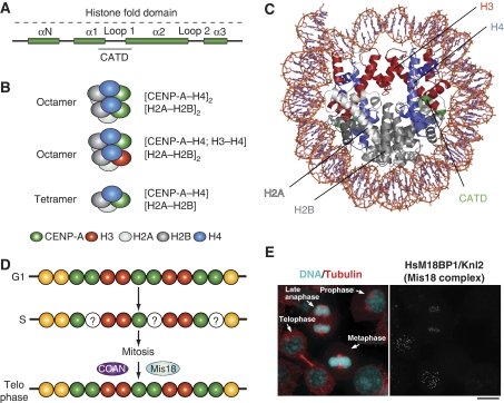
Kinetochores are large protein assemblies built on chromosomal loci named centromeres. The main functions of kinetochores can be grouped under four modules. The first module, in the inner kinetochore, contributes a sturdy interface with centromeric chromatin. The second module, the outer kinetochore, contributes a microtubule-binding interface. The third module, the spindle assembly checkpoint, is a feedback control mechanism that monitors the state of kinetochore-microtubule attachment to control the progression of the cell cycle. The fourth module discerns correct from improper attachments, preventing the stabilization of the latter and allowing the selective stabilization of the former. In this review, we discuss how the molecular organization of the four modules allows a dynamic integration of kinetochore-microtubule attachment with the prevention of chromosome segregation errors and cell-cycle progression.


Figures

Figure 1
Figure 1
The kinetochore of S. cerevisiae. (A) The 125 bp centromere of S. cerevisiae is subdivided in the CDEI, CDEII, and CDEIII regions. The 8 bp CDEI recruits a dimer of Cbf1, a helix-turn-helix protein that runs a parallel life as a transcription factor (Bram and Kornberg, 1987). CDEII, a 76–84 bp AT-rich DNA element, folds around a specialized nuclesome containing Cse4 (Meluh et al, 1998; Keith and Fitzgerald-Hayes, 2000). The four-subunit CBF3 complex is only found in species whose centromeres contain a CDE-III motif (Meraldi et al, 2006). CBF3 binds to the CDE-III motif, an imperfect palyndrome with an approximately 24 bp ‘core' and a less well-conserved CDE-II-distal sequence of 50–60 bp (Lechner and Carbon, 1991). Additionally, at least one CBF3 subunit, Ndc10, is also found in association with CDE-II (Espelin et al, 2003). (B) The Cse4-containing nucleosome wraps around the approximately 125 bp centromeric DNA (black). Mif2p (homologous to CENP-C) is a linker protein creating a connection with the Mtw1, Spc105, and Ndc80 complexes (homologous to Mis12, KNL-1, and Ndc80 complexes of higher eukaryotes). Together with the Dam1 complex, the Ndc80 complex reaches the microtubule-binding region. The Ipl1p complex is equivalent to the chromosome passenger complex (CPC) of higher eukaryotes. The Nbl1p subunit was recently identified as a homologue of the Borealin/DasraB/CSC-1 subunit of higher eukaryotes (Nakajima et al, 2009). It is believed to span from the inner to the outer region of the kinetochore. The kinase activity associated with this complex is directed onto the Ndc80 and Dam1 complexes and regulates the attachment process. Names of constituent subunits are displayed. (C) Average location of kinetochore proteins along the axis of the S. cerevisiae's kinetochore–microtubule attachment in metaphase and late anaphase (Joglekar et al, 2009). N- and C- indicated N- and C-termini.
Figure 2
Figure 2
Organization of regional centromeres and kinetochores. (A) The central domain of the centromere of S. pombe possesses a pair of inverted repeat sequence arrays (marked as imr, for innermost repeat). They flank an unconserved central core sequence. Both CENP-A and H3-containing nucleosomes map to the central domain. The central domain is flanked by the cohesin-rich outer domains, consisting of peri-centromeric heterochromatin. In humans, α-satellite DNA is composed of a core of highly ordered 171 bp repeats termed α-I satellite DNA, which is framed on either side by divergent repetitive sequences and retrotransposons, referred to as α-II satellite DNA. At the outskirts, the centromeric chromatin becomes rich in long interspersed element 1 (LINE-1 elements). On normal human chromosomes, the centromere forms on a small subdomain of the α-I satellite DNA, but there are cases in which the centromere forms on DNA devoid of α-satellite repeats. The α-I satellite DNA contains a sequence known as the CENP-B box, which binds in a sequence-specific manner to the CENP-B protein and facilitates, but is not strictly required for, kinetochore formation. The panel was adapted from Allshire and Karpen (2008) (B) Adjacent kinetochores from a metaphase cell obtained by rapid freezing and freeze substitution (reproduced from ref. McEwen et al, 1998). The prominent outer plate (op) structure stains as heavily as chromatin, and is separated from the underlying inner plate (ip) by a well-defined, translucent, middle layer (ml). Bar represents 200 nm. (C) Electron tomography of the outer plate shows a network of crosslinked fibres, 10 nm in diameter and up to 80–90 nm long, of unknown molecular identity. The long fibres aligned in the plane of the outer plate in the absence of microtubules (not shown), but re-oriented as they bound to the side of microtubules (Dong et al, 2007). (D) A scheme for the outer kinetochore of metazoans analogous to that presented in Figure 1B. (E) Average location of kinetochore proteins along the axis of the kinetochore–microtubule attachment in metaphase in D. melanogaster. N- and C- indicated N- and C-termini.
Figure 3
Figure 3
Bi-orientation, erroneous attachments. A single sister chromosome pair is shown for simplicity. In amphitelic orientation (bi-orientation) each of the two opposing sister kinetochores is bound to microtubules originating from the proximal pole. This is the correct form of attachment. Monotelic attachment is a normal condition during prometaphase before bi-orientation. Premature loss of sister chromatid cohesion at this early stage, for instance as a consequence of a cohesion defect or a mitotic checkpoint defect, can yield aberrant segregation with both sister chromatids distributed to the same daughter cell. Persistent cohesion between chromosomes in anaphase will result in similar errors. In syntelic attachment, both sisters in a pair connect to the same pole. In merotelic attachment, a sister is attached to both poles. This condition occurs quite frequently during mitosis.
Figure 4
Figure 4
Epigenetic specification of centromeric chromatin. (A) The histone-fold domain of histone H3 proteins is composed of four α-helical domains (αN and α1–α3). Loop 1 separates α1 and α2. The CENP-A targeting domain (CATD) is sufficient for localization to centromeres when substituted into canonical H3 (the amino acids highlighted in orange are required in Drosophila). The CATD was identified for a 10-fold slowing of hydrogen exchange along the peptide backbone, probably because of increase rigidity of the interface it forms with its histone H4 (Black et al, 2004). (B) In non-centromeric regions, canonical histone H3 assembles into octameric nucleosomes composed of two H2A, H2B, H3, and H4 histone subunits. In centromeric chromatin, CENP-A can assemble into homotypic octamers, in which both H3 subunits are replaced by CENP-A, or into heterotypic octamers, which contain one canonical H3 and one CENP-A subunit. In Drosophila melanogaster, CENP-A has been reported to form half nucleosomes, homotypic tetramers containing one subunit each of H2A, H2B, H4, and CENP-A/CID. (C) Ribbond model of the nucleosome core particle (PDB ID 2CV5). Histone H3 is in red. When grafted onto histone H3, the CATD of CENP-A (green) allows specific and selective incorporation of the H3 chimaera at the centromere. The CENP-A2:H42 tetramers are more compact and rigid than the H32:H42 tetramers (Black et al, 2004). (D) CENP-A is only replenished in telophase. Thus, chromatin entering S phase with a full complement of CENP-A, emerges from DNA replication with half the original levels. The halved levels are retained throughout mitosis. (E) The localization pattern of M18BP1, a subunit of the Mis18 complex. The figure derives from Maddox et al (2007). The dots on the right panel represent centromeres/kinetochores.
Figure 5
Figure 5
Biased diffusion. Binding of candidate couplers to microtubule ends can be monitored experimentally by tethering the coupler at the surface of beads, and then monitoring bead motion. Three kinds of tethering to microtubule ends can be distinguished experimentally at this time: (1) Dam1-dependent rings generate high forces. The attached beads do not roll (Grishchuk et al, 2008a). The structure of the Dam1 complex is discussed in Figure 6; (2) Ring-independent Dam1 coupling in which the bead does roll as the MT shortens (Grishchuk et al, 2008b); (3) Motor-dependent tethering in which beads do not roll (Grissom et al, 2009). The mechanism of this coupling is still unknown. Two additional modes of movement have been proposed: (1) biased diffusion, as originally proposed in Hill's model (Hill, 1985) and more recently for the Ndc80 complex (Powers et al, 2009); and (2) power strokes from bending protofilaments acting on non-diffusing, MT-binding fibrils (McIntosh et al, 2008). (A) With a ring coupler encircling a microtubule (inspired by the Dam1 ring, discussed in Figure 6), force may be provided by flared depolymerizing protofilaments, which exercise a pressure against the base of the sleeve. (B) Hill's model depicts the microtubule-binding site of the kinetochore as a ‘sleeve' surrounding the microtubule (Hill, 1985). The microtubule-binding sites are represented by triangles. Maximization of the number of binding sites drives the sliding of the sleeve along the microtubule. The design and theoretical treatment of (BF) are largely based on earlier work (Joglekar and Hunt, 2002; Powers et al, 2009). (C) The overall activation energy required for sliding along the lattice may cause diffusion to be slow or fast. To be effective, diffusion has to occur with kinetics that must be compatible with the kinetics of microtubule depolymerization. (D) An alternative mechanism for biased diffusion based on the Ndc80 complex was recently proposed (Powers et al, 2009). Kinetochores are shown as red hollow discs. The coupler is an elongated molecule with two globular domains at either end, one for kinetochore binding and one for microtubule binding, and it is inspired by the Ndc80 complex (see Figure 6). Coupling is along the lattice and is mediated by five microtubule-binding elements. The free-energy landscape for this coupler is shown on the right. l denotes spacing of sites. The red circle represents the current position of the coupler on the surface. The energy landscape is corrugated because movement along the filament requires breaking and reforming some bonds (C). b is the activation energy, w is the binding energy. The triangle represents a fiduciary mark along the microtubule. (E) The microtubule has depolymerized and the coupler has diffused on the surface towards the plus end. (F) The release of the coupler (two out of five binding sites have been lost here) implies an increase in free energy because the bond energies, w, must be overcome to move the couple past the filament tip. The heights of the activation energies 5b, 4b,…., b, decrease as the coupler begins to move past the tip. (G) The bottom row shows tomographic slices of kinetochore microtubule ends. The same gallery is also shown in the top row with protofilaments and their associated kinetochore fibrils, indicated by graphic overlays. (H) A tomographic reconstruction of a kinetochore–microtubule interface with associated fibrils. (G, H) are from McIntosh et al (2008).
Figure 6
Figure 6
The molecular machinery of kinetochore–microtubule attachment. (A) Topology of the Ndc80 complex. Ndc80 and Nuf2 engage in a dimer. They contain N-terminal CH domains followed by a coiled-coil region that mediates inter-subunit interactions. Spc24 and Spc25 have N-terminal coiled-coils that mediate inter-subunit interactions, followed by globular domains that are responsible for binding to the Mis12 complex. Tetramerization engages the C-terminal region of the Ndc80:Nuf2 dimer and the N-terminal region of the Spc24:Spc25 dimer. aa, amino acids. N and C indicate the N- and C-termini, respectively. (A, D) were reproduced from Ciferri et al (2008). (B) Gallery of three individual Ndc80 complexes. Arrowheads mark a prominent kink along the shaft. The scale bar corresponds to 10 nm. The images are reproduced from Wang et al (2008). (C) By fusing the C-termini of the Ndc80 and Nuf2 subunits to the N-termini of the Spc25 and Spc24 subunits, respectively, a ‘bonsai' version of the Ndc80 complex was created. Most of the coiled-coil in the central shaft was deleted. The resulting complex retains the ability to bind microtubules in vitro and to localize to kinetochores when injected into living cells (Ciferri et al, 2008). (D) Overall view of the 2.9 Å crystal structure of the bonsai-Ndc80 complex (PDB ID 2VE7). The two CH domains pack in a tight dimeric assembly. An 80-residue N-terminal disordered segment in the Ndc80 subunit escaped structure determination (dashed line). Together with the globular region of Ndc80:Nuf2, this segment contributes to microtubule binding. (E) A model of the full length Ndc80 complex. The model is based on earlier electron microscopy work on the Ndc80 complex (Wei et al, 2005; Wang et al, 2008) and on a crosslinking and mass spectrometry analysis that identified the register of coiled-coil interaction within the central shaft (Maiolica et al, 2007). The regions contained in the crystal structure of bonsai-Ndc80 are boxed. The coiled-coil is interrupted by a 50-residue insertion in the Ndc80 sequence that increases the overall flexibility of the Ndc80 rod. (F) Left: negatively stained control microtubules stabilized with GMPCPP, a non-hydrolysable GTP analogue that stabilizes the microtubule lattice. Middle: negatively stained GMPCPP microtubules in the presence of 5 μM Ndc80 complex (C. elegans). The Ndc80 complex forms angled rod-like projections on the microtubule lattice. Right: traces of the EM images depicting the angled rod-like complexes bound to the lattice. Scale bars represent 200 nm. The panel was reproduced from Cheeseman et al (2006). (G) Negative stain electron microscopy of Dam1 rings assembled around microtubules in vitro. Bar=50 nm. The panel reproduced from Westermann et al (2005). (H) The Dam1 complexes are heterodecamers. They contain one copy each of 10 essential budding yeast proteins. Dam1 rings form by oligomerization of individual complexes around microtubules.
Figure 7
Figure 7
Models of kinetochore assembly. (A) ‘Epistatic' relationships between kinetochore proteins. Arrows indicate a dependency for localization, where the pointed end indicates a protein(s) that requires proteins at the barbed end for kinetochore localization. The list of proteins shown here is not comprehensive. The circles enclosing a ‘P' indicate post-translational modifications. (B) The vertical layout. Kinetochore proteins ultimately converge on a single Cse4p/CENP-A nucleosome (e.g. Joglekar et al, 2009). Given that there are 6–8 KMN network complexes per Cse4/CENP-A nucleosome, it is sensible to assume that this special nucleosome is placed directly below the microtubule, approximately on the same axis, with the different KMN network surrounding the microtubule roughly equidistantly (only two KMN complexes are shown here). (C) The horizontal model. Rather than being placed along an idealized vertical line from the inner to the outer kinetochore, the kinetochore components are distributed horizontally. Specifically, the KMN network components are linked to the kinetochore core by Mif2p/CENP-C, but are also establishing specific contacts with H3 nucleosomes through CENP-T/W.
Figure 8
Figure 8
‘Repeat subunit' models. (A) A transverse section through the K-fibre of a metaphase PtK1 cell, showing multiple microtubules. Bar=0.5 μM, magnification × 60000. Source of figure is from Rieder (1981). (B) Horizontal clustering of modules (only two are shown) may explain the distribution of microtubules in the K-fibre shown in (A). (C) The solenoid model. Left: centromere stretching experiment indicating that the array of CENP-A nucleosomes, coalesced in three-dimensional space, are not contiguous along the DNA but are interrupted by spacers containing blocks of H3-containing nucleosomes. The image was reproduced from Blower et al (2002). Right: CENP-A nucleosome coalescence could be entirely self-directed, or alternatively, it might necessitate the action of bridging factors—perhaps components of the CCAN—to organize into the array that forms the foundation of the mitotic kinetochore. The panel is an adaptation from Black and Bassett (2008). (D) Three distinct hypothetical patterns of CENP-A and H3 nucleosomes with different ratios of H3 to CENP-A. CENP-A is always shown at the centre, and is surrounded by H3. (E) The pattern at the bottom of (D) is now shown to ‘coalesce' in a larger assembly. (F) Speculative pattern of deposition of CCAN and KMN modules on the pattern shown in (E). CCAN is on CENP-A nucleosomes, whereas KMN goes to H3 nucleosomes.
Figure 9
Figure 9
Error correction and the spindle checkpoint. (A) Schematic description of the geometry of the centromere–kinetochore interface in the absence and presence of tension. (B) The boxed area in (A) enlarged. Phosphorylation of certain substrates at the centromere–kinetochore interface is constitutive (the yellow circle marked by ‘P'), that is the substrate is phosphorylated with or without tension. Other substrates are only phosphorylated in the absence of tension, because their separation from the centromere exceeds a threshold value when tension is present. (C) Left: schematic description of the CPC complex. Right: the CPC occupies the centromere, and only a subset of complexes is located near the centromere–kinetochore interface. (D) A comprehensive model of checkpoint control and error correction. In the absence of tension, either substrate like Ndc80 become phosphorylated by Aurora B or by other kinases whose activation requires Aurora B. This creates a condition for SAC activation through the recruitment of SAC proteins (Ditchfield et al, 2003; Hauf et al, 2003). On the other hand, the phosphorylation of Ndc80 decreases the binding affinity for microtubules (Cheeseman et al, 2006; DeLuca et al, 2006; Ciferri et al, 2008). This creates a state of labile attachment that will become corrected unless a force is applied. The removal of Ndc80 and possibly other substrates from the reach of Aurora B stabilizes the attachment through the action of a phosphatase.

Similar articles

Cited by

References

    1. Alexander SP, Rieder CL (1991) Chromosome motion during attachment to the vertebrate spindle: initial saltatory-like behavior of chromosomes and quantitative analysis of force production by nascent kinetochore fibers. J Cell Biol 113: 805–815 - PMC - PubMed
    1. Allshire RC, Karpen GH (2008) Epigenetic regulation of centromeric chromatin: old dogs, new tricks? Nat Rev Genet 9: 923–937 - PMC - PubMed
    1. Ando S, Yang H, Nozaki N, Okazaki T, Yoda K (2002) CENP-A, -B, and -C chromatin complex that contains the I-type alpha-satellite array constitutes the prekinetochore in HeLa cells. Mol Cell Biol 22: 2229–2241 - PMC - PubMed
    1. Andrews PD, Ovechkina Y, Morrice N, Wagenbach M, Duncan K, Wordeman L, Swedlow JR (2004) Aurora B regulates MCAK at the mitotic centromere. Dev Cell 6: 253–268 - PubMed
    1. Asbury CL, Gestaut DR, Powers AF, Franck AD, Davis TN (2006) The Dam1 kinetochore complex harnesses microtubule dynamics to produce force and movement. Proc Natl Acad Sci USA 103: 9873–9878 - PMC - PubMed

Publication types

Substances