. 2009 Aug 21;9(16):2286-92.
doi: 10.1039/b908978k. Epub 2009 May 15.

SlipChip

Affiliations

SlipChip

Wenbin Du et al. Lab Chip. .

Abstract

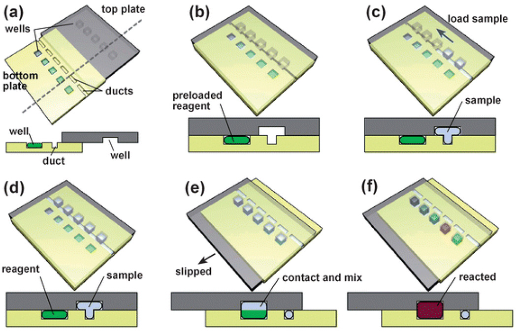
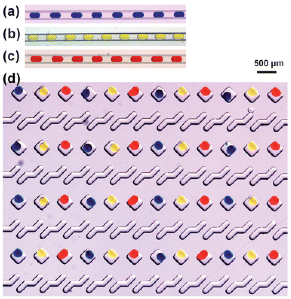
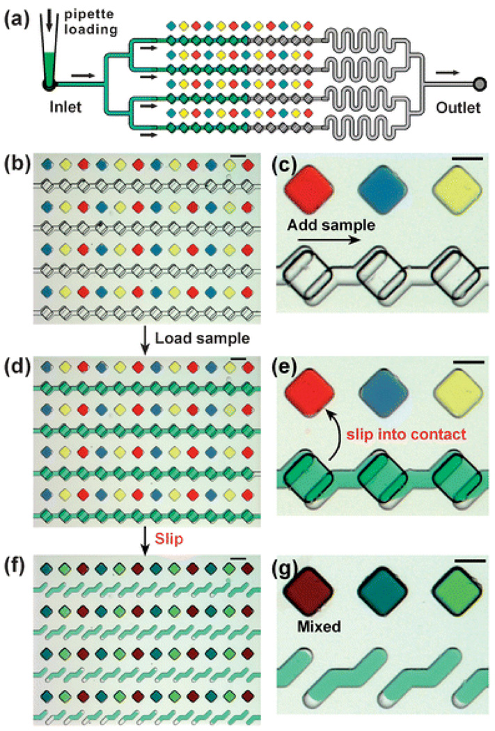
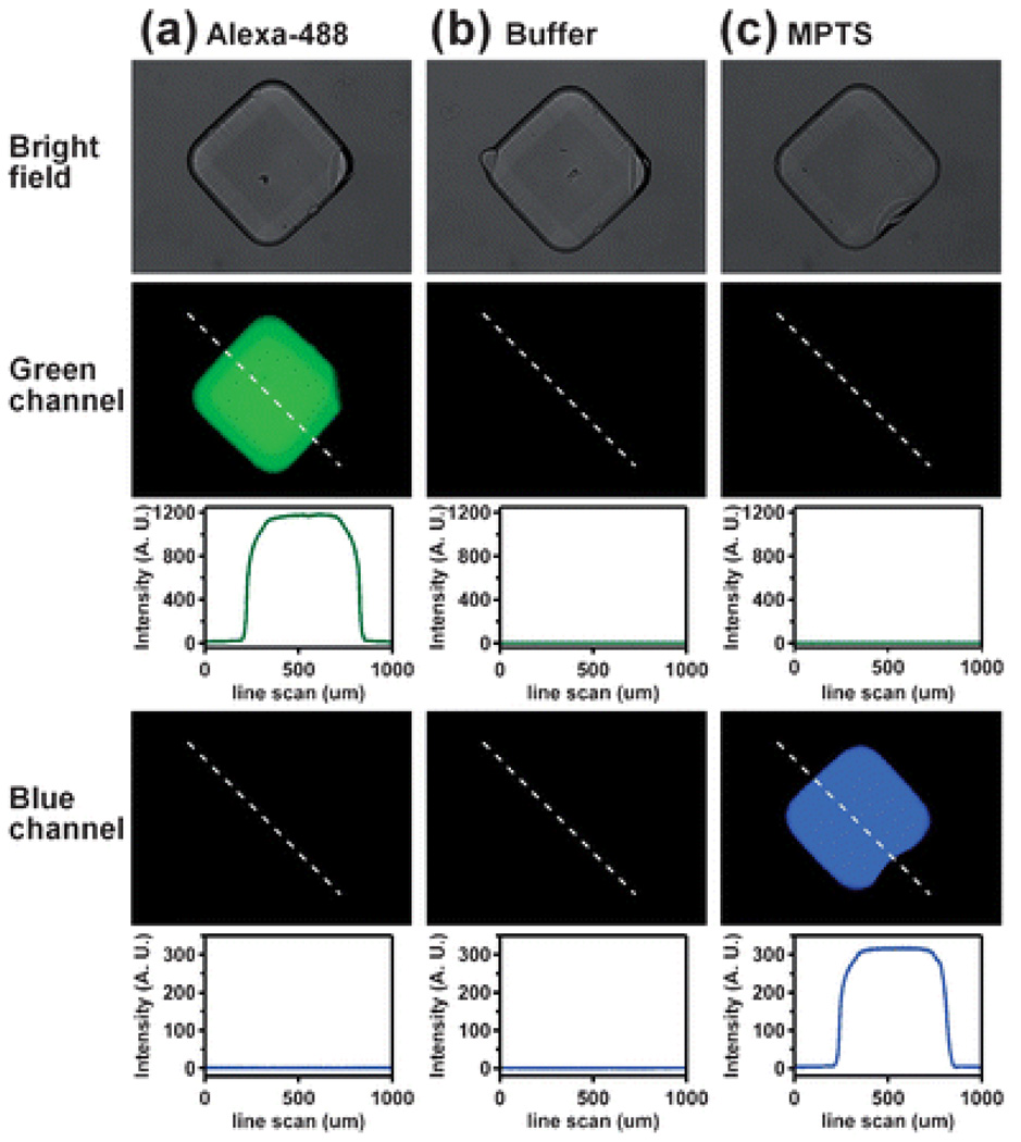
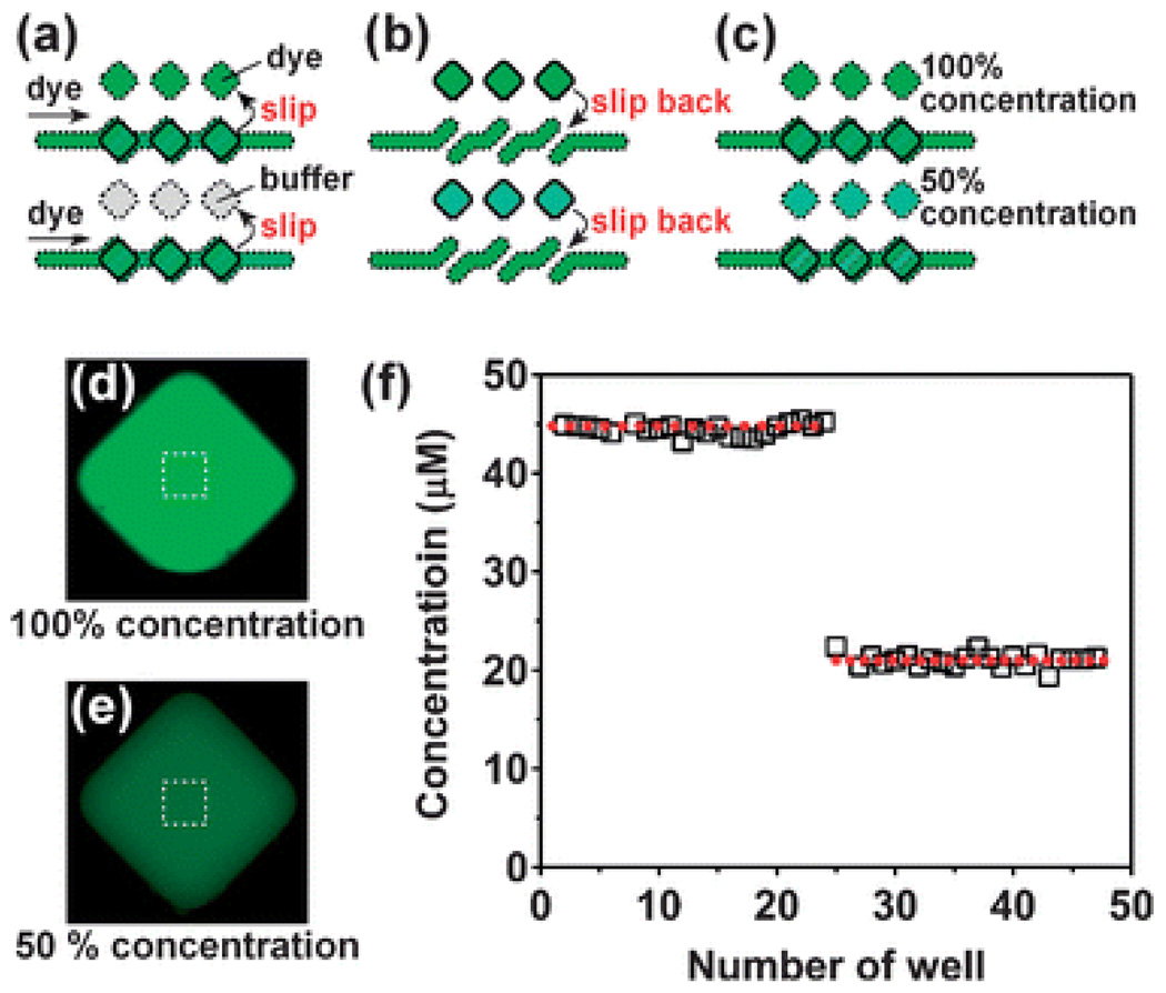
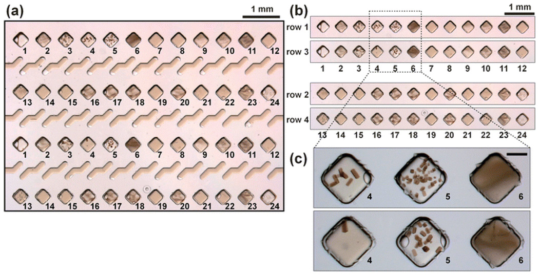
The SlipChip is a microfluidic device designed to perform multiplexed microfluidic reactions without pumps or valves. The device has two plates in close contact. The bottom plate contains wells preloaded with many reagents; in this paper plates with 48 reagents were used. These wells are covered by the top plate that acts as a lid for the wells with reagents. The device also has a fluidic path, composed of ducts in the bottom plate and wells in the top plate, which is connected only when the top and bottom plate are aligned in a specific configuration. Sample can be added into the fluidic path, filling both wells and ducts. Then, the top plate is "slipped", or moved, relative to the bottom plate so the complementary patterns of wells in both plates overlap, exposing the sample-containing wells of the top plate to the reagent-containing wells of the bottom plate, and enabling diffusion and reactions. Between the two plates, a lubricating layer of fluorocarbon was used to facilitate relative motion of the plates. This paper implements this approach on a nanoliter scale using devices fabricated in glass. Stability of preloaded solutions, control of loading, and lack of cross-contamination were tested using fluorescent dyes. Functionality of the device was illustrated via crystallization of a model membrane protein. Fabrication of this device is simple and does not require a bonding step. This device requires no pumps or valves and is applicable to resource-poor settings. Overall, this device should be valuable for multiplexed applications that require exposing one sample to many reagents in small volumes. One may think of the SlipChip as an easy-to-use analogue of a preloaded multi-well plate, or a preloaded liquid-phase microarray.


Figures

Fig. 1
Fig. 1
Step-by-step 3D schematic drawings with cross-sectional views that describe the operation of the SlipChip. (a) Off-set view that shows the preloaded wells of the bottom plate, the ducts of the bottom plate, and the wells of the top plate. (b) View of the device available to the user, in which the top and bottom plates are aligned. (c) and (d) Loading of a single sample through the overlapping ducts of the bottom plate and wells of the top plate. (e) Slipping of the top plate relative to the bottom plate disconnects the sample wells of the top plate from the ducts of the bottom plate, and then exposes the sample wells to the wells of the bottom plate containing reagents. (f) The red well schematically shows a reaction taking place after mixing and incubation (see also movie S1†).
Fig. 2
Fig. 2
(a), (b) and (c) Microphotographs of plugs with uniform volumes of food dye solutions stored in Teflon tubing. The plugs were formed in a flow focusing device in three separate experiments. (d) Microphotograph of the wells in the bottom plate of a SlipChip. The wells were loaded with plugs of the solutions of food dye in a repeating pattern.
Fig. 3
Fig. 3
Operation of the SlipChip illustrated experimentally with food dyes. (a) A top-down schematic drawing of pipetting sample into the SlipChip used in the experiments. (b) A top-down microphotograph of a glass SlipChip with 48 reagent wells preloaded with red, blue, and yellow solutions of food dyes. (c) A zoomed-in microphotograph of the device shown in (b). (d) A top-down microphotograph of the SlipChip shown in (b) after the ducts and wells were filled. Filling was done by pipetting 0.5 µL of a solution of green food dye into the inlet. (e) A zoomed-in microphotograph of device shown in (d). (f) A top-down microphotograph of the SlipChip shown in (d) after the top plate was slipped to expose the sample wells to the reagent wells. Ducts filled with the solution of green food dye are visible. (g) A zoomed-in microphotograph of the device shown in (f). Scale bars for (b), (d) and (f) are 500 µm and for (c), (e) and (g) are 250 µm.
Fig. 4
Fig. 4
No cross-contamination was detected in the preloaded SlipChip after 12 hours. Bright-field microphotograph (top), fluorescent microphotograph through the green channel (exciter: 480/40 nm; emitter: 527/30 nm) and corresponding intensity profile, and fluorescent microphotograph through the blue channel (exciter: 360/40 nm; emitter: 470/40 nm) and corresponding intensity profile are shown for the wells filled with (a) Alexa-488 dye, (b) buffer (10 mM Tris pH 7.8), and (c) MPTS dye.
Fig. 5
Fig. 5
Filling and mixing of reagents on the SlipChip was consistent. (a) A schematic drawing of the SlipChip in which the reagent wells were preloaded with buffer and a fluorescent solution, with the same fluorescent solution added into the ducts and sample wells. (b) A schematic drawing of the same device after the slip. (c) A schematic drawing of the device after the top plate was slipped back to separate the sample from the well. (d) Fluorescent microphotograph of a well of 100% Alexa-488. (e) Fluorescent microphotograph of a well of 50% Alexa-488. (f) Concentration of the dye in wells 1–24 had a coefficient of variation of 3.9% (n = 23). Concentration of the dye in the remaining wells (25–48) had a coefficient of variation of 3.2% (n = 22), confirming accuracy and precision of both filling and mixing.
Fig. 6
Fig. 6
The crystallization conditions of the photosynthetic reaction center from Blastochloris viridis was screened against two sets of 24 precipitants in duplicate on the SlipChip. (a) A microphotograph of the SlipChip containing 48 crystallization trials after incubation for two hours. This image corresponds to the SlipChip after loading precipitants, adding solution of the protein, and slipping (as in Fig. 3f). Different precipitants are labeled as 1 through 24. Conditions 4 and 5 produced crystals in both sets of wells. (b) Side-by-side comparison of row 1 with row 3 and row 2 with row 4, illustrating reproducibility of the results between the duplicate sets of experiments. (c) Microphotographs of conditions 4, 5, and 6, which contained the same precipitant ((NH4)2SO4) with concentrations of 3.2 M, 3.6 M, and 4.0 M. As expected, a transition from a single crystal, to multiple crystals, to heavy precipitation was observed with the increase in precipitant concentration. The scale bar is 250 µm.

Similar articles

Cited by

References

    1. Duffy DC, Gillis HL, Lin J, Sheppard NF, Kellogg GJ. Anal. Chem. 1999;71:4669–4678.
    1. Chiu DT, Jeon NL, Huang S, Kane RS, Wargo CJ, Choi IS, Ingber DE, Whitesides GM. Proc. Natl. Acad. Sci. USA. 2000;97:2408–2413. - PMC - PubMed
    1. Dertinger SKW, Chiu DT, Jeon NL, Whitesides GM. Anal. Chem. 2001;73:1240–1246.
    1. Thorsen T, Maerkl SJ, Quake SR. Science. 2002;298:580–584. - PubMed
    1. Moerman R, van Dedem GWK. Anal. Chem. 2003;75:4132–4138. - PubMed

Publication types

MeSH terms

Substances