. 2010 Jan 1;49(1):561-7.
doi: 10.1016/j.neuroimage.2009.07.033. Epub 2009 Jul 28.

Anatomical atlas-guided diffuse optical tomography of brain activation

Affiliations

Anatomical atlas-guided diffuse optical tomography of brain activation

Anna Custo et al. Neuroimage. .

Abstract

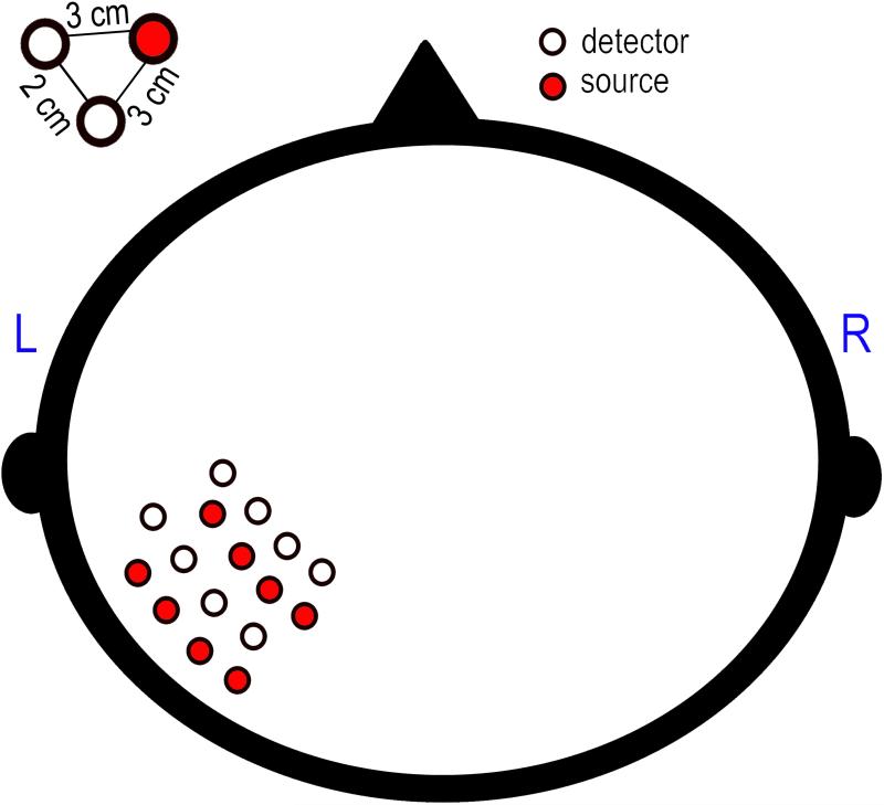
We describe a neuroimaging protocol that utilizes an anatomical atlas of the human head to guide diffuse optical tomography of human brain activation. The protocol is demonstrated by imaging the hemodynamic response to median-nerve stimulation in three healthy subjects, and comparing the images obtained using a head atlas with the images obtained using the subject-specific head anatomy. The results indicate that using the head atlas anatomy it is possible to reconstruct the location of the brain activation to the expected gyrus of the brain, in agreement with the results obtained with the subject-specific head anatomy. The benefits of this novel method derive from eliminating the need for subject-specific head anatomy and thus obviating the need for a subject-specific MRI to improve the anatomical interpretation of diffuse optical tomography images of brain activation.


Figures

Figure 1
Figure 1
On the subject's head (a) we place the physical probe (b) and acquire optical measurements. We register the MNI atlas (C) to the subject's scalp using SLR10-20 (A) and then project the locations of the probe onto the registered atlas scalp (B). Having defined the virtual probe on the registered atlas, we simulate photon migration on the registered atlas using a Monte Carlo algorithm, producing the sensitivity matrix which, combined with the optical measurements, forms the input of the DOT inverse problem.
Figure 2
Figure 2
Linear fitting of the data points from the CSF-age study of Custo et al. (2008) (correlation coefficient 0.57 with significance p << 0.005): the black circles represent the CSF thickness median over the sampled scalp points. To customize the atlas to the target subject, we estimate the subject's median CSF thickness given its age from this linear model. Then we dilate or erode the registered atlas’ CSF layer to match the subject's estimated value.
Figure 3
Figure 3
The experimental probe is designed to cover the left hemisphere motor and pre-motor cortex. The probe consists of eight sources (red) and eight detectors (white) in a 4×4 grid. Each detector/source is set 2 cm apart from the closest detector/source and 3 cm apart from the closest source/detector.
Figure 4
Figure 4
Localizing activation: the subject (left) and corresponding registered atlas (right) activation maps are plotted on the cortical surfaces (pink shade) and the scalp surfaces are shaded in gray; the sources (blue circles) and detectors (black circles) locations are also shown. The activation contrast has been thresholded at half maximum (colorbar is arbitrary).
Figure 5
Figure 5
Localizing vascular response to brain activation in the three experimental subjects a, b and c (one for each column); the subject- (top row, RECONs, one subject per column) and corresponding registered atlas-based reconstructed activation maps (second row, RECONa) are plotted on the cortical surfaces (pink shade). The bottom row shows the overlap of the top and middle rows: the blue area is the active region from the second row (atlas-based), the red area is the active region from the top row (subject-based), and the overlap of these two areas is showed in yellow. The activation contrast has been thresholded at half maximum, for better visualization and to focus the comparison between subject- and atlas-based reconstructions on the spatial localization rather than on the signal amplitude, and therefore the colorbar is arbitrary. Subject (a) and (c) show activation in the anterior bank of the ventral section (a) and dorsal section (c) of the post-central gyrus (primary somatosensory area, SI); subject (b)'s highest hemodynamic response is registered in the secondary somatosensory area (SII), in the posterior bank of the post-central gyrus due to lack of optodes probing the SI region.
Figure 6
Figure 6
Reconstructed brain activation in subject c using FreeSurfer surface representaion tools. The top row shows the active regions in RECONs on the pial surface (left) and on the inflated cortical surface (right), the second row shows the response obtained using RECONa, and the bottom row shows the overlap (yellow) of RECONa (blue) and RECONs (red) reconstructed active areas. The activation focus is on the dorsal section of the post-central gyrus (Brodmann areas 3, 1, and 2).

References

    1. Arienzo D, Babiloni C, Ferretti A, Caulo M, Del Gratta C, Tartaro A, Rossini P, Romani G. Somatotopy of anterior cingulate cortex (acc) and supplementary motor area (sma) for electric stimulation of the median and tibial nerves: an fmri study. NeuroImage. 2006;33(2):700–5. - PubMed
    1. Arridge S. Optical tomography in medical imaging. Inverse Problems. 1999;15(2):41–93. topical review.
    1. Aslin R, Mehler J. Near-infrared spectroscopy for functional studies of brain activity in human infants: promise, prospects, and challenges. J Biomed Opt. 2005;10(1):11009. - PubMed
    1. Bertero M, Boccacci P. Introduction to Inverse Problems in Imaging. 1998. IOP Publishing.
    1. Bluestone AY, Abdoulaev G, Schmitz CH, Barbour RL, Hielscher AH. Three-dimensional optical tomography of hemodynamics in the human head. Opt. Express. 2001;9(6):272–286. - PubMed

Publication types

MeSH terms

LinkOut - more resources