. 2009 Jul 23:2:12.
doi: 10.3389/neuro.16.012.2009. eCollection 2009.

A low-cost multielectrode system for data acquisition enabling real-time closed-loop processing with rapid recovery from stimulation artifacts

Affiliations

A low-cost multielectrode system for data acquisition enabling real-time closed-loop processing with rapid recovery from stimulation artifacts

John D Rolston et al. Front Neuroeng. .

Abstract

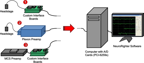
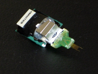
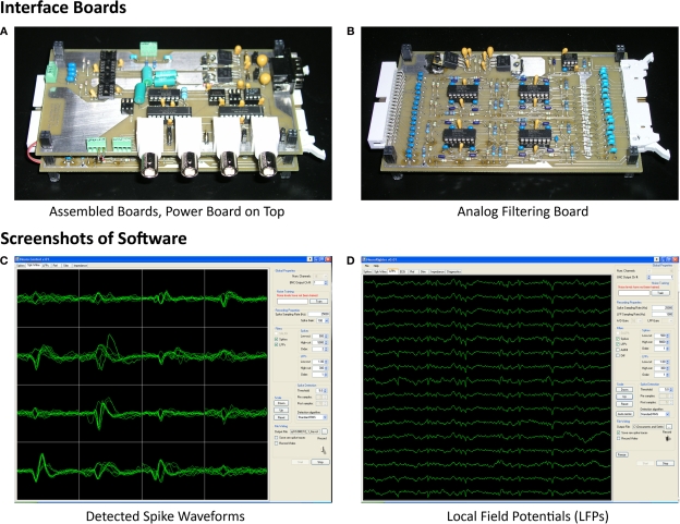
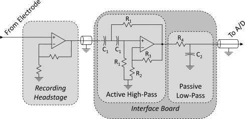
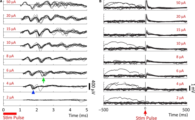
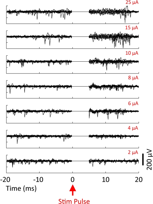
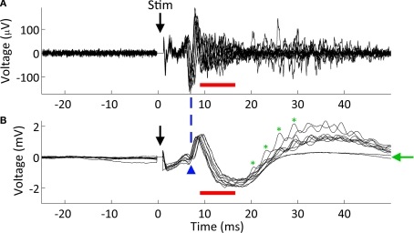
Commercially available data acquisition systems for multielectrode recording from freely moving animals are expensive, often rely on proprietary software, and do not provide detailed, modifiable circuit schematics. When used in conjunction with electrical stimulation, they are prone to prolonged, saturating stimulation artifacts that prevent the recording of short-latency evoked responses. Yet electrical stimulation is integral to many experimental designs, and critical for emerging brain-computer interfacing and neuroprosthetic applications. To address these issues, we developed an easy-to-use, modifiable, and inexpensive system for multielectrode neural recording and stimulation. Setup costs are less than US$10,000 for 64 channels, an order of magnitude lower than comparable commercial systems. Unlike commercial equipment, the system recovers rapidly from stimulation and allows short-latency action potentials (<1 ms post-stimulus) to be detected, facilitating closed-loop applications and exposing neural activity that would otherwise remain hidden. To illustrate this capability, evoked activity from microstimulation of the rodent hippocampus is presented. System noise levels are similar to existing platforms, and extracellular action potentials and local field potentials can be recorded simultaneously. The system is modular, in banks of 16 channels, and flexible in usage: while primarily designed for in vivo use, it can be combined with commercial preamplifiers to record from in vitro multielectrode arrays. The system's open-source control software, NeuroRighter, is implemented in C#, with an easy-to-use graphical interface. As C# functions in a managed code environment, which may impact performance, analysis was conducted to ensure comparable speed to C++ for this application. Hardware schematics, layout files, and software are freely available. Since maintaining wired headstage connections with freely moving animals is difficult, we describe a new method of electrode-headstage coupling using neodymium magnets.

Keywords: data acquisition system; hippocampus; local field potential; microstimulation; multi-electrode array; population spike; recording; stimulation artifact.


Figures

Figure 1
Figure 1
System overview illustrating multiple use cases. ❶ A head-mounting amplifier (headstage) buffers multielectrode signals and sends them to custom interface PCBs. These boards provide filtered power to the recording headstage and an analog band-pass filter for the acquired neural signals. ❷ A Plexon headstage sends amplified neural signals to a Plexon preamplifier, which provides further amplification and band-pass filtering for the acquired signals. ❸ A MultiChannel Systems (MCS) preamplifier amplifies and filters neural signals from substrate integrated MEAs. Power is supplied by custom interface boards, as in ❶. In all cases, signals are digitized with a National Instruments PCI-6259 data acquisition card, hosted by a standard desktop computer. Acquisition, visualization, and recording are controlled through our open-source NeuroRighter software.
Figure 2
Figure 2
Neodymium magnets to secure headstage. Strong, “rare earth” magnets are glued to both the implanted microwire array, and the recording headstage. These magnets ensure a firm connection during normal animal movement, while nevertheless allowing the connection to break with sufficiently high forces (e.g., the experimenter's desire to end a recording, or an animal's particularly violent motions). A breakable connection helps to prevent loss of the acrylic headcap.
Figure 3
Figure 3
Photographs of interface PCBs and screenshots of NeuroRighter Software. (A) The stacking of one power board and an analog filter board is shown. Components on the power board handle power filtering and voltage regulation (upper right of board). Additional components are for future stimulation and EEG-recording applications (Rolston et al., 2007, 2008), not described in this article. The power board and filtering board beneath are connected with stackthrough connectors. (B) Analog filtering boards provide a regulated power supply to each recording headstage and filter acquired data from each channel (including the reference channel) through a two-pole active high-pass filter (ICs, resistors, and capacitors on the board's left and middle) and a passive one-pole low-pass filter (resistors and capacitors on right of board). (C) The open-source NeuroRighter software provides visualization of detected action potential (“spike”) waveforms across all recording channels (16, shown in a 4 × 4 grid). Multiple methods for action potential detection are available. (D) LFPs are recorded from each channel by digitally band-pass filtering the raw data and downsampling. Five seconds of data are drawn for each of 16 channels. Recordings are from the hippocampus of an awake and behaving rat (see Experimental Methods).
Figure 4
Figure 4
Signal chain from electrode to A/D card. Signals originate from a microwire electrode and are amplified within the recording headstage in reference to a common ground. These signals propagate to the interface PCB, where they are band-pass filtered, and then to the A/D card. The band-pass filter is composed of a two-pole active high-pass filter (voltage-controlled voltage-source topology, as in (Horowitz and Hill, 1989) and a one-pole passive low-pass filter. Resistors labeled R1 and capacitors labeled C1 determine the −3 dB point of the high-pass filter, and R4 and C2 determine the −3dB point of the low-pass filter. R2 and R3 determine the nature of the high-pass filter (e.g., Butterworth, Bessel, etc.).
Figure 5
Figure 5
Signal processing steps. A raw signal is acquired, then split into two signals by digital filtering (blue arrows at top of figure). Low frequency data is downsampled and referred to as the local field potential (LFP). High frequency data is used to detect action potentials, or “spikes.” A user-defined threshold is used to detect candidate spike waveforms (green arrow in middle of diagram). Detected action potentials are indicated with red and green circles. Multiple 3-ms waveforms are extracted (red arrow, lower right). The two colors, red and green, indicate that the spikes likely arise from different cells, given their different waveforms. Data were recorded with our system from the dorsal hippocampus (CA3) of an awake, behaving rat.
Figure 6
Figure 6
Noise spectra. (A) Averaged, electrode-referred broadband spectra for a 16 channel system. Shading represents 95% confidence interval. The black curve depicts the noise spectrum with a grounded reference; the red curve shows data acquired with a true reference. (B) Noise spectra in the action potential frequency band, compared to noise spectrum from a Plexon preamplifier (blue), which has a 1-pole analog band-pass filter set to 300–8800 Hz. Red, black, and shading are as in (A). Note the harmonics present in the Plexon amplifier's spectrum. This is likely due to ground loops within the system, since the Plexon system is not battery-powered and has multiple paths to ground.
Figure 7
Figure 7
Stimulation through a 560 kΩ resistor. A custom stimulator, interposed between the recording headstage and electrodes (which, in this case, were simulated by 560 kΩ resistors connected to ground), was used to evaluate stimulation artifacts on the stimulating electrode and neighboring electrodes. Stimuli lasting 800 μs were delivered at 0 ms. The average of 10 trials of ±10 μA biphasic stimuli (negative, cathodic phase first) are shown in each panel. 95% error bars are too small to be resolvable at this magnification, and are therefore not displayed. Gray bands represent the ±100 μV recovery window – see text for definition of recovery and desaturation. Artifact durations are provided in Table 1 for non-stimulated electrodes and Table 2 for stimulated electrodes. The analog band-pass filter of the Plexon spike band (A) is 300–8800 Hz. The Plexon LFP bandwidth is 1–500 Hz (B). No digital filtering is used for the TBSI-based NeuroRighter system (C).
Figure 8
Figure 8
10 μA Stimulation through a microwire array immersed in ACSF. Biphasic (negative, cathodic phase first) pulses were delivered to each channel. The average of 10 trials is shown in each panel. 95% error bars are too small to be resolvable at this magnification, and are therefore not displayed. Gray bands represent the ±100 μV recovery window. Artifact durations for the non-stimulating electrodes are provided in Table 1, while durations for the stimulated electrode are shown in Table 2. (A) The Plexon system's spike band is 300–8800 Hz. (B) The LFP band is 1–500 Hz. (C) The TBSI headstage (NeuroRighter system) was digitally filtered >300 Hz to compare with the Plexon system's spike band. (D) No digital filtering was used for TBSI broadband recordings.
Figure 9
Figure 9
Directly evoked neural responses to stimulation in vivo. Responses to current-controlled microstimulation of increasing amplitude (amplitude shown in red) recorded from a non-stimulating electrode in an anesthetized rat's hippocampus (CA1). All pulses are cathodic, negative-phase first. Ten trials are overlaid in each panel. Trial amplitude was randomized during presentation. (A) The first evoked action potentials appear at ≥4 μA, within 1 ms of stimulus offset (blue arrowhead), followed by an additional response at ≥6 μA (green arrow). Artifacts are suppressed digitally using the SALPA algorithm (Wagenaar and Potter, 2002). (B) LFP responses show increasing durations of attenuation (flattening) in LFP activity with increasing stimulation currents, corresponding to inhibition of neuronal firing. Viewing these LFP responses would not be possible with the Plexon system, due to its long stimulation artifact.
Figure 10
Figure 10
Evoked response recorded on the stimulating electrode. Biphasic current-controlled stimuli were delivered at time 0 ms to the hippocampus of an awake, behaving rat. Ten trials of each intensity are overlaid. Spontaneous APs are clearly visible before stimulation and evoked APs after blanking. The SALPA artifact suppression algorithm is used to digitally remove residual stimulation artifact, and to blank the channel for 5 ms.
Figure 11
Figure 11
Microstimulation responses in CA3 of an epileptic animal. Simultaneously recorded (A) action potential traces (using the SALPA filter) and (B) LFP responses. Ten responses to a 20 μA biphasic pulse (negative phase first) are overlaid in both (A) and (B). The stimulating electrode was located 175 μm distant in the same cell layer, CA3. As shown previously (Andersen et al., 1971), single cell activity underlies population spikes (blue arrowhead). However, we noted a high amount of multiunit activity following the population spike that is not clearly associated with any additional spike (red bars). Lastly, we observed evoked high frequency oscillations at ∼300 Hz (in the fast ripple range) in 80% of trials (green asterisks mark four periods of one such oscillation). The green arrow denotes the two traces where no fast ripples were evoked.

References

    1. Andersen P., Bliss T. V., Skrede K. K. (1971). Unit analysis of hippocampal polulation spikes. Exp. Brain Res. 13, 208–22110.1007/BF00234086 - DOI - PubMed
    1. Arsiero M., Luscher H. R., Giugliano M. (2007). Real-time closed-loop electrophysiology: towards new frontiers in in vitro investigations in the neurosciences. Arch. Ital. Biol. 145, 193–209 - PubMed
    1. Bakkum D. J., Chao Z. C., Potter S. M. (2008). Long-term activity-dependent plasticity of action potential propagation delay and amplitude in cortical networks. PLoS ONE 3, e2088.10.1371/journal.pone.0002088 - DOI - PMC - PubMed
    1. Berger T. W., Ahuja A., Courellis S. H., Deadwyler S. A., Erinjippurath G., Gerhardt G. A., Gholmieh G., Granacki J. J., Hampson R., Hsaio M. C., LaCoss J., Marmarelis V. Z., Nasiatka P., Srinivasan V., Song D., Tanguay A. R., Wills J. (2005). Restoring lost cognitive function. IEEE Eng. Med. Biol. Mag. 24, 30–4410.1109/MEMB.2005.1511498 - DOI - PubMed
    1. Berger T. W., Glanzman D. (2005). Toward Replacement Parts for The Brain: Implantable Biomimetic Electronics as Neural Prostheses. Cambridge, MA, MIT Press