. 2009;46(3):315-30.
doi: 10.1682/jrrd.2008.09.0123.

Mathematical modeling and mechanical and histopathological testing of porous prosthetic pylon for direct skeletal attachment

Affiliations

Mathematical modeling and mechanical and histopathological testing of porous prosthetic pylon for direct skeletal attachment

Mark Pitkin et al. J Rehabil Res Dev. 2009.

Abstract

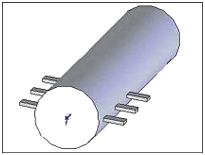
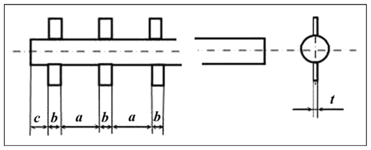
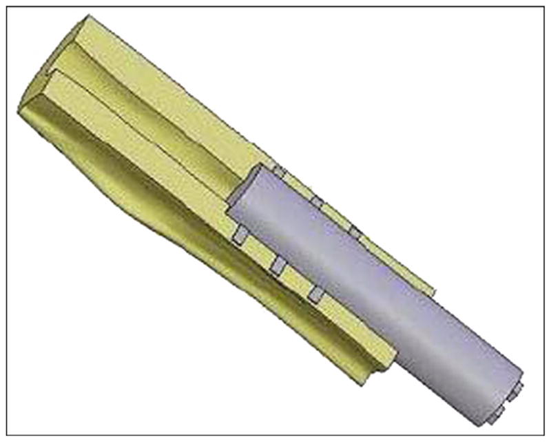
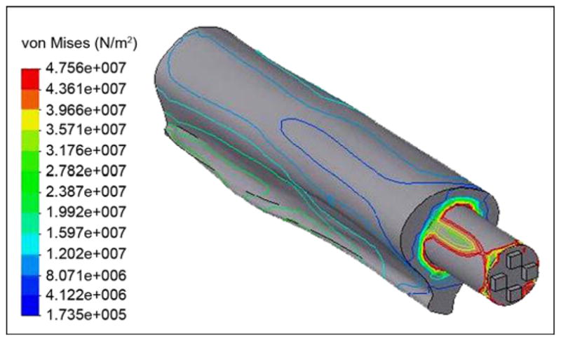
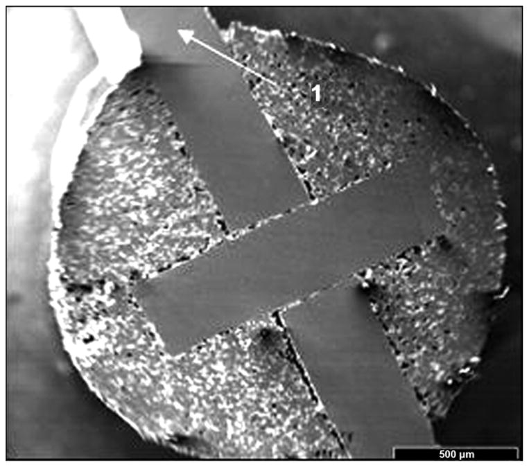
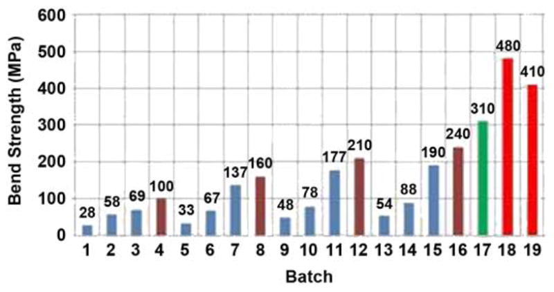
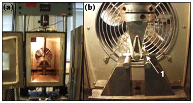
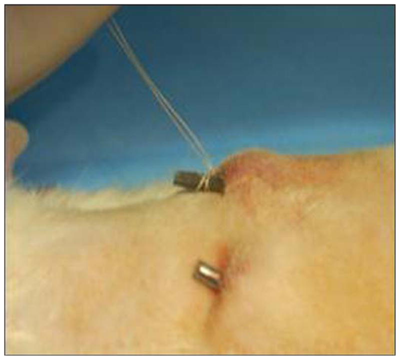
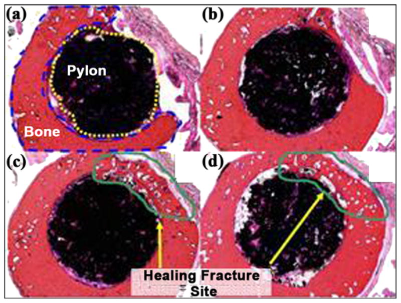
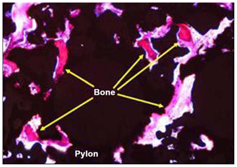
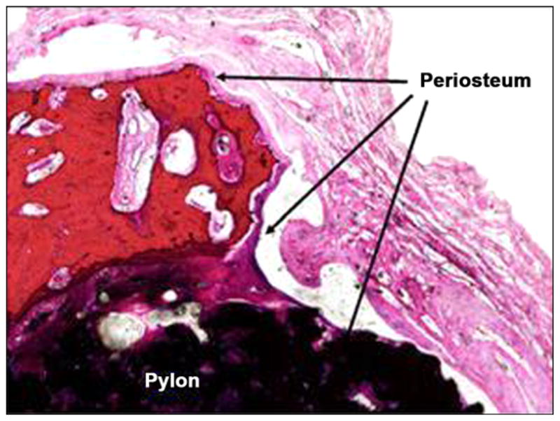
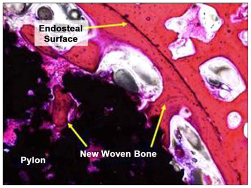
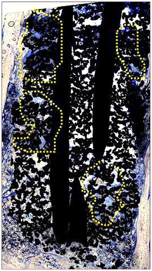
This article presents recent results in the development of the skin and bone integrated pylon (SBIP) intended for direct skeletal attachment of limb prostheses. In our previous studies of the porous SBIP-1 and SBIP-2 prototypes, the bond site between the porous pylons and residuum bone and skin did not show the inflammation characteristically observed when solid pylons are used. At the same time, porosity diminished the strength of the pylon. To find a reasonable balance between the biological conductivity and the strength of the porous pylon, we developed a mathematical model of the composite permeable structure. A novel manufacturing process was implemented, and the new SBIP-3 prototype was tested mechanically. The minimal strength requirements established earlier for the SBIP were exceeded threefold. The first histopathological analysis of skin, bone, and the implanted SBIP-2 pylons was conducted on two rats and one cat. The histopathological analysis provided new evidence of inflammation-free, deep ingrowth of skin and bone cells throughout the SBIP structure.


Figures

Figure 1
Figure 1
Cross section of cross-shaped insert with single hole drilled through one rib at axis of hole (blue = solid titanium, yellow = porous titanium, white = no material). Numbers represent percentage of radius length.
Figure 2
Figure 2
Tensile and flexural moduli of the two reinforcing geometries as function of level of porosity in matrix, together with modulus of porous solid alone. CROSS = cross-shaped insert, 3 WIRE = porous cylinder reinforced with three wires.
Figure 3
Figure 3
Potential reduction in flexural and tensile moduli from holes of given diameter in web of solid insert. Dotted line indicates relative modulus of pylon, P(φ), consisting solely of porous solid with 35% by volume.
Figure 4
Figure 4
Three-dimensional computer-aided design model of femur bone fragment used in finite element analysis.
Figure 5
Figure 5
Three-dimensional computer-aided design model of the pylon with three pairs of fins 1 (skin and bone integrated pylon 3).
Figure 6
Figure 6
Dimensions a, b, c, and t of fins 1 (skin and bone integrated pylon 3).
Figure 7
Figure 7
Three-dimensional computer-aided design model of skin and bone integrated pylon 3 implanted in bone fragment.
Figure 8
Figure 8
Von Mises stress distributions in bone-pylon system (outer view).
Figure 9
Figure 9
Schematic of application of force (F) and moments (torsional [L1], bending [L2], transversal [L3]) to distal end of pylon.
Figure 10
Figure 10
Von Mises stress distributions in bone-pylon system in medial-lateral cross section for skin and bone integrated pylon 3 with fins. See Figure 9 for stress distribution scale.
Figure 11
Figure 11
Von Mises stress distributions in bone-pylon system in medial-lateral cross section for cylindrical skin and bone integrated pylon 2. See Figure 9 for stress distribution scale.
Figure 12
Figure 12
Base of graphite mold (1) and frame assembly of 10 double inserts (2). After sintering, skin and bone integrated pylon 3 was cut out along lines (3, 4).
Figure 13
Figure 13
Cross-frame insert with outside fins in skin and bone integrated pylon 3 prototype.
Figure 14
Figure 14
Bend strength of tested samples. Session I: batches 1–4, session II: batches 5–8, session III: batches 9–12, session IV: batches 13–16, session V: batch 17, session VI: batch 18, and session VII: batch 19.
Figure 15
Figure 15
(a) Setup of servo-hydraulic testing machine for fatigue tests at Case Western Reserve University and (b) magnified view of skin and bone integrated pylon 3 sample (1).
Figure 16
Figure 16
Fixation of implanted skin and bone integrated pylon (SBIP-2) in rat study.
Figure 17
Figure 17
Tissue and rod in methyl methacrylate block before slide preparation.
Figure 18
Figure 18
Scanning electron microscopic image of bond between outer part (1) and insert (2) of skin and bone integrated pylon 3. Magnification: (a) 18×, (b) 100×, (c) 100×, and (d) 250×.
Figure 19
Figure 19
Orientation of device in skin (both images 1×, hematoxylin and eosin stain) after 3 weeks of implantation in rats.
Figure 20
Figure 20
Close-up of fine fibrovascular tissue within implant pores: (a) rat 452E09397A (40×, hematoxylin and eosin [HE] stain) at 3 weeks after implantation and (b) rat 4662162459 (20×, HE stain) at 9 weeks after implantation.
Figure 21
Figure 21
(a)–(d) Cross sections of pylon device in bone from distal to proximal (2×, all hematoxylin and eosin stain).
Figure 22
Figure 22
Periosteum covering fractured bone and device (4×, hematoxylin and eosin stain).
Figure 23
Figure 23
Bone formation in pores at center of device (10×, hematoxylin and eosin stain).
Figure 24
Figure 24
New woven bone on endosteal surface and extending into device pores (10×, hematoxylin and eosin stain).
Figure 25
Figure 25
New bone extending into device pores, as indicated by yellow highlighted regions (4× composite image, toluidine blue stain).

Similar articles

Cited by

References

    1. Brånemark R, Brånemark PI, Rydevik B, Myers RR. Osseo-integration in skeletal reconstruction and rehabilitation: A review. J Rehabil Res Dev. 2001;38(2):175–81. - PubMed
    1. Pitkin M. On the way to total integration of the prosthetic pylon with residuum. J Rehabil Res Dev. 2009;43(6):345–60. - PMC - PubMed
    1. Pitkin M, Blinova MI, Yudintseva NV, Potokin IL, Raykhtsaum G, Pinaev GP. Skin and bone integrated prosthetic technology. I. Characterization and morphology of human cells cultivated on titanium implants of different structures [abstract]. Proceedings of the 9th Russian National Congress, People and Health; 2004 Nov 22–26; St. Petersburg, Russia. St. Petersburg (Russia): Russian National Congress; 2004. p. 217.
    1. Pitkin M, Raykhtsaum G, inventors. Skin integrated device. United States patent US. 20070071788. 2007. Mar 29,
    1. Von Recum AF. Applications and failure modes of percutaneous devices: A review. J Biomed Mater Res. 1984;18(4):323–36. doi: 10.1002/jbm.820180403. - DOI - PubMed

Publication types