Comparative Study
. 2009 Sep;136(3):460-70.
doi: 10.1016/j.ajodo.2009.04.016.

Working with DICOM craniofacial images

Affiliations
Comparative Study

Working with DICOM craniofacial images

Dan Grauer et al. Am J Orthod Dentofacial Orthop. 2009 Sep.

Abstract

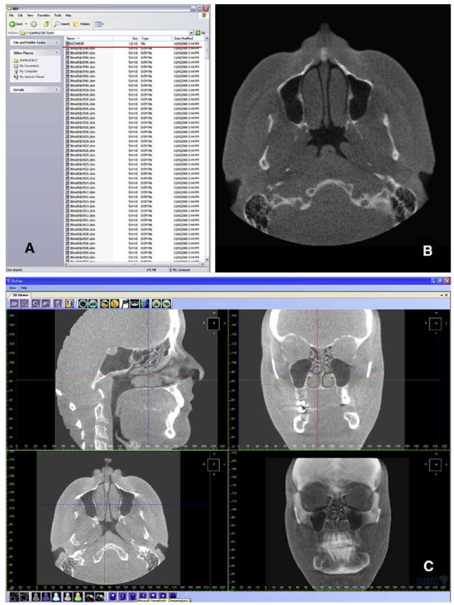
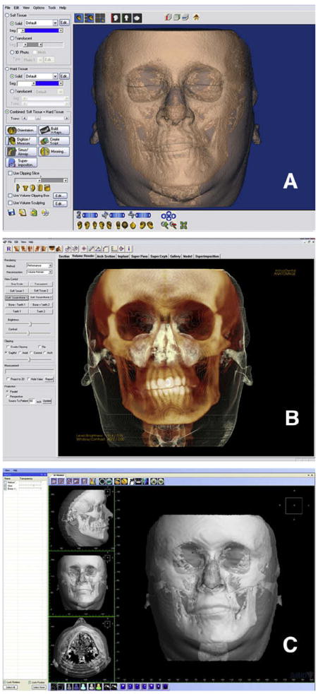
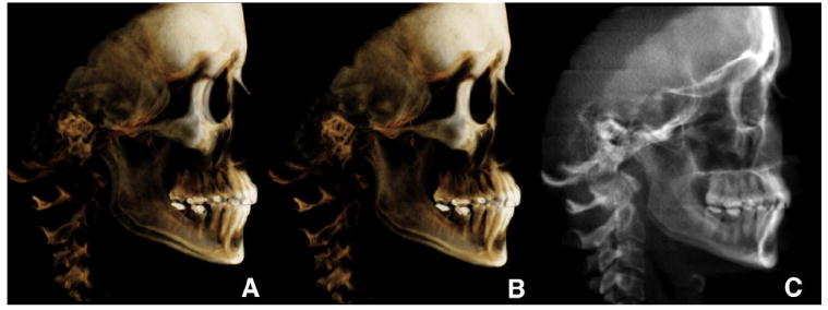
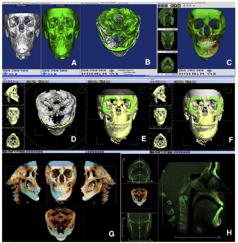
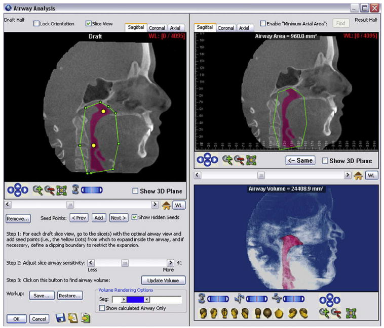
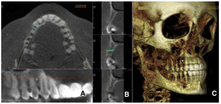
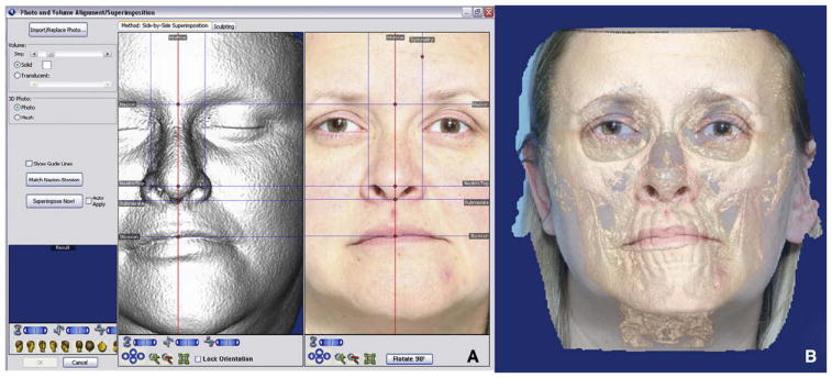
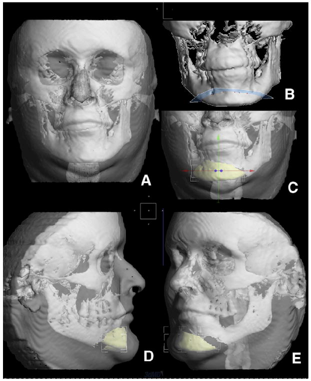
The increasing use of cone-beam computed tomography (CBCT) requires changes in our diagnosis and treatment planning methods as well as additional training. The standard for digital computed tomography images is called digital imaging and communications in medicine (DICOM). In this article we discuss the following concepts: visualization of CBCT images in orthodontics, measurement in CBCT images, creation of 2-dimensional radiographs from DICOM files, segmentation engines and multimodal images, registration and superimposition of 3-dimensional (3D) images, special applications for quantitative analysis, and 3D surgical prediction. CBCT manufacturers and software companies are continually working to improve their products to help clinicians diagnose and plan treatment using 3D craniofacial images.


Figures

Fig 1
Fig 1. Example of a DICOM record
A, DICOMDIR file (red underline) and sequential axial slices; B, an axial slice; C, reformatted stack of slices allows the user to scroll in any direction (saggital, coronal, axial). Three-dimensional view of the CBCT volume is also available (3dMDvultus Software).
Fig 2
Fig 2. Different visualization modes and interfaces of 3 programs
A, Dolphin Imaging interface, with thresholding filters applied to visualize both hard and soft tissues, and a semitransparency applied to the soft tissue to visualize the hard tissue underneath; B, InVivoDental volume interface, with modified thresholding filters applied by a preset visualization “Soft tissue + Bone 1”; C, 3dMDvultus software interface, with hard- and soft-tissue surface models created (segmentations) and a semi-transparency applied to the soft-tissue segmentation.
Fig 3
Fig 3. Creation of synthetic cephalograms
A, unoriented volume; B, oriented to obtain the correct head rotation (note the difference between the orbits and zygomatic bone); C, once oriented, the cephalogram was generated or has been generated (InVivoDental).
Fig 4
Fig 4. Registration and superimposition of sequential CBCT images
A, Dolphin Imaging uses a landmark-based registration process that allows the user to manually refine the relative position of the CBCT images until, B, stable structures are matching. C, Once registered, semitransparency visualization allows the user to measure and assess changes. D, The 3dMDvultus software uses a surface-based registration process in which the first 2 images are manually positioned; E, anatomically stable surfaces are selected, and the program refines the registration by matching those surfaces; once registered, changes can be determined. F, Surgical outcome assessment—in this case, maxillary advancement, autorotation of the mandible and genioplasty—can be measured and visualized in the volumetric rendered image and the stack of slices. G and H, Different InVivoDental visualizations of the registered volumes.
Fig 5
Fig 5
Airway analysis module by Dolphin Imaging: at the upper right corner, the airway passages are segmented by initialization spheres. Both area and volume can be calculated. The airway segmentation can be rotated, panned, and zoomed in space.
Fig 6
Fig 6. Implant simulation and arch section module in InVivoDental
A, a microimplant is virtually placed between the roots of the maxillary right canine and first premolar; B, cortical bone thickness can be measured as well as total bone; C, InVivoDental also allows 3D visualization to assess anatomic relationships. The position on the implant can be modified with 6 degrees of freedom.
Fig 7
Fig 7. Matching a 2D picture on the 3D soft-tissue volume
A, homologous landmarks are located in the volume and the 2D picture; B, Dolphin Imaging registers both images to create a multimodal image. Note the eye difference between the 2 modalities. There might be other, less-obvious areas of discrepancy between photographic and CBCT data.
Fig 8
Fig 8. Three-dimensional surgical simulation by the 3dMDvultus software
A, surface models were created for both hard and soft tissues; B, virtual surgical osteotomies are performed—here, a lower border osteotomy (genioplasty); C, the chin segment is slid to the left to correct the asymmetry and also moved forward for illustration purposes; D and E, changes predicted in the soft tissues.

References

    1. DICOM digital imaging and communications in medicine. Rosslyn,Va: National Electrical Manufacturers Association (NEMA); 2008.
    1. Cevidanes LH, Styner MA, Proffit WR. Image analysis and superimposition of 3-dimensional cone-beam computed tomography models. Am J Orthod Dentofacial Orthop. 2006;129:611–8. - PMC - PubMed
    1. Jerrold L. Liability regarding computerized axial tomography scans. Am J Orthod Dentofacial Orthop. 2007;132:122–4. - PubMed
    1. Bookstein FL. Landmark methods for forms without landmarks: morphometrics of group differences in outline shape. Med Image Anal. 1997;1:225–43. - PubMed
    1. Oliveira AE, Cevidanes LH, Phillips C, Motta A, Burke B, Tyndall D. Observer reliability of three-dimensional cephalometric landmark identification on cone-beam computerized tomography. Oral Surg Oral Med Oral Pathol Oral Radiol Endod. 2000;107:256–65. - PMC - PubMed

Publication types

MeSH terms