. 2010 Jan;29(1):146-58.
doi: 10.1109/TMI.2009.2030679. Epub 2009 Sep 9.

Intersection based motion correction of multislice MRI for 3-D in utero fetal brain image formation

Affiliations

Intersection based motion correction of multislice MRI for 3-D in utero fetal brain image formation

Kio Kim et al. IEEE Trans Med Imaging. 2010 Jan.

Abstract

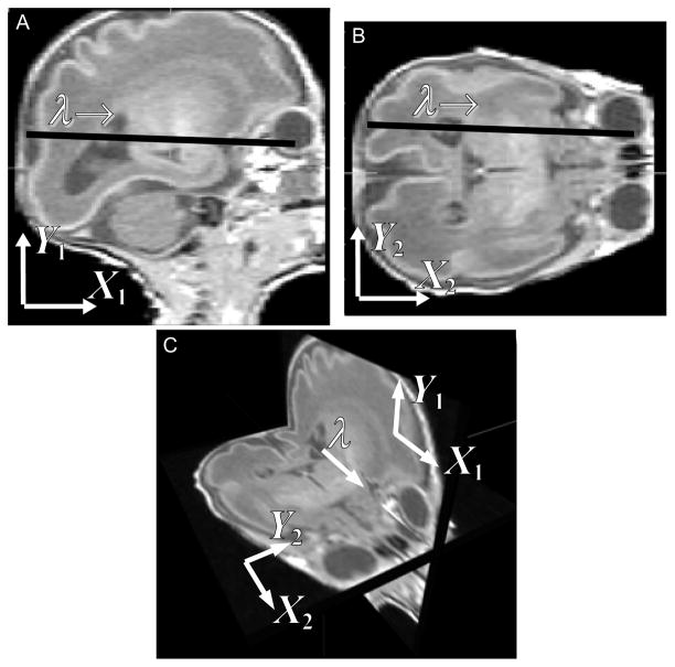
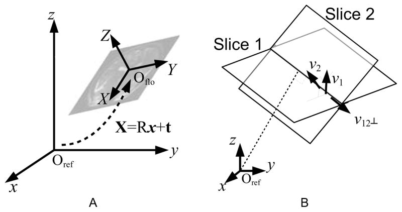
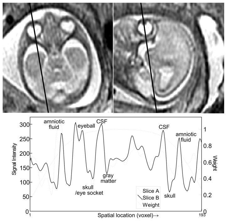
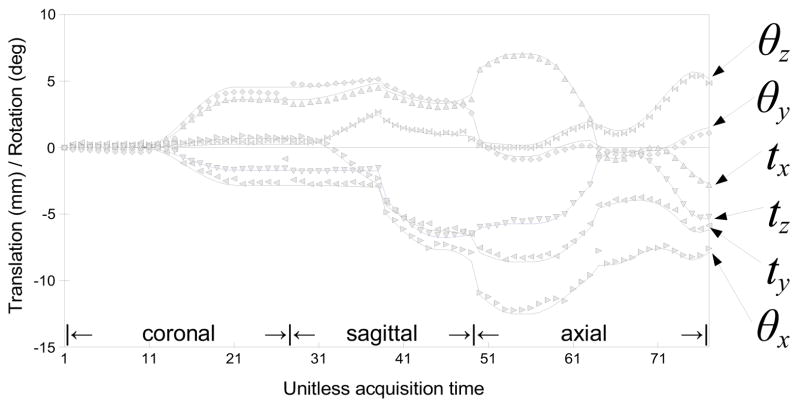
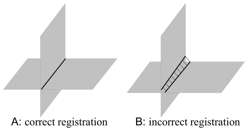
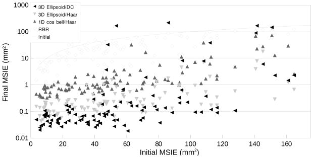
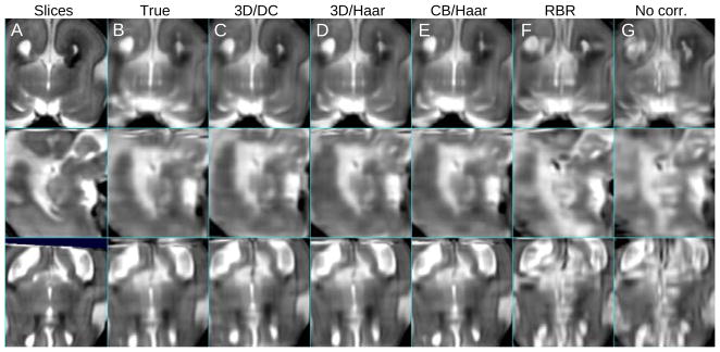
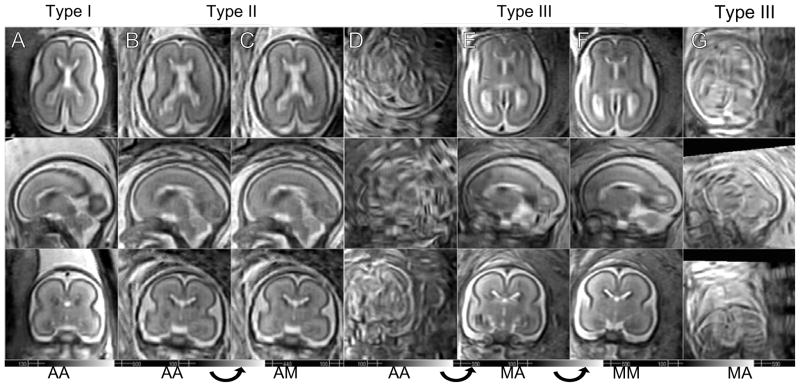
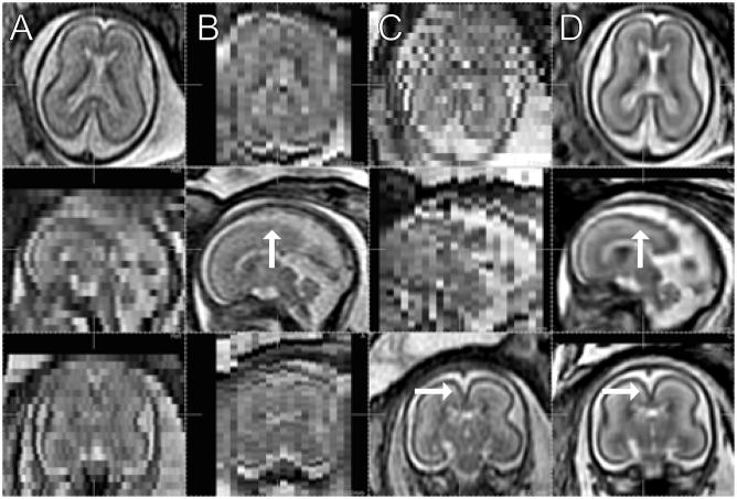
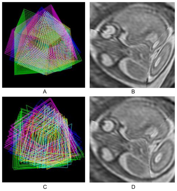
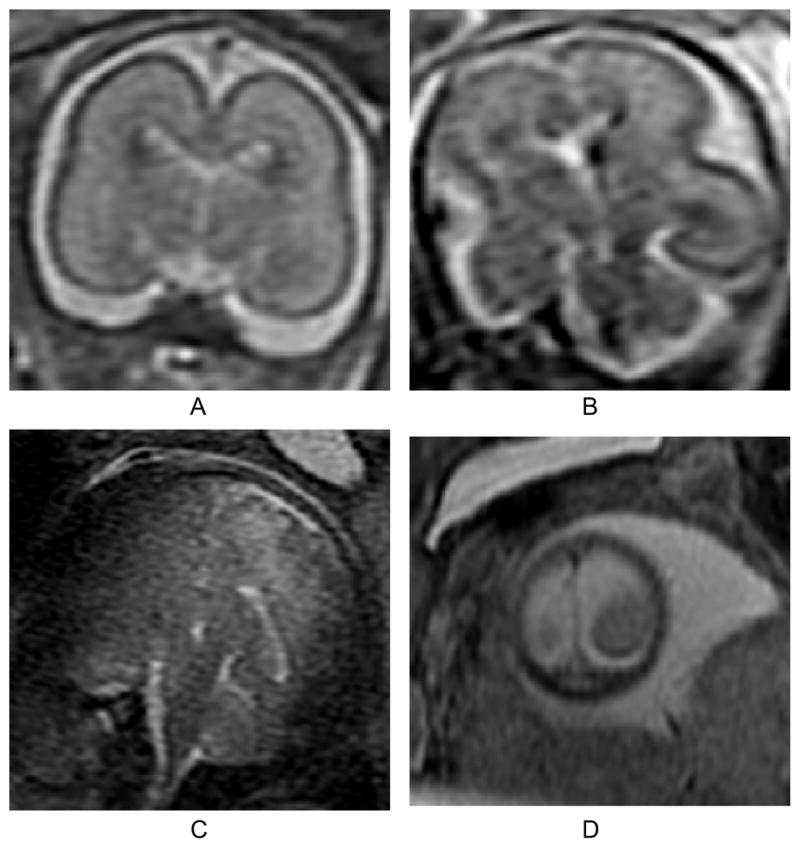
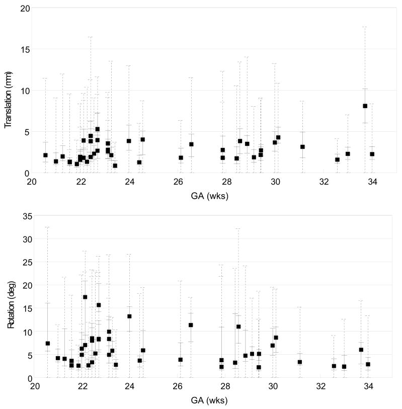
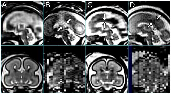
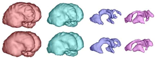
In recent years, postprocessing of fast multislice magnetic resonance imaging (MRI) to correct fetal motion has provided the first true 3-D MR images of the developing human brain in utero. Early approaches have used reconstruction based algorithms, employing a two-step iterative process, where slices from the acquired data are realigned to an approximate 3-D reconstruction of the fetal brain, which is then refined further using the improved slice alignment. This two step slice-to-volume process, although powerful, is computationally expensive in needing a 3-D reconstruction, and is limited in its ability to recover subvoxel alignment. Here, we describe an alternative approach which we term slice intersection motion correction (SIMC), that seeks to directly co-align multiple slice stacks by considering the matching structure along all intersecting slice pairs in all orthogonally planned slices that are acquired in clinical imaging studies. A collective update scheme for all slices is then derived, to simultaneously drive slices into a consistent match along their lines of intersection. We then describe a 3-D reconstruction algorithm that, using the final motion corrected slice locations, suppresses through-plane partial volume effects to provide a single high isotropic resolution 3-D image. The method is tested on simulated data with known motions and is applied to retrospectively reconstruct 3-D images from a range of clinically acquired imaging studies. The quantitative evaluation of the registration accuracy for the simulated data sets demonstrated a significant improvement over previous approaches. An initial application of the technique to studying clinical pathology is included, where the proposed method recovered up to 15 mm of translation and 30 degrees of rotation for individual slices, and produced full 3-D reconstructions containing clinically useful additional information not visible in the original 2-D slices.


Figures

Fig. 1
Fig. 1
When two orthogonally planned slice stacks cover a common volume, each slice in one stack always intersects with the slices in the other stack. A sagittal slice (A) and an axial slice (B) from simulated MR image stacks of a premature infant are shown. Panel A and B are viewed in the 3D space in panel C. Two slices can be registered by adjusting the transformation parameters so as to improve the match of their intersection intensity profiles.
Fig. 2
Fig. 2
(A) The reference frame, and the floating frame of one slice. The two coordinate systems are related by six motion parameters—three for translation (t) and three for rotation (R). (B) Parametrization of the intersection location. The parameter λ is 0 at the projection of the origin of the reference space onto the intersection line, and increases as it extends along the intersection direction, namely, v12⊥
Fig. 3
Fig. 3
The intersection between two orthogonally planned slices. (GA 22 weeks under normal development, TR/TE = 4500/90.) The bottom panel shows the two intersection profiles of the slices, and 1D profile of the 3D ellipsoidal windowing function.
Fig. 4
Fig. 4
Basis functions for motion estimation: (A) Haar basis functions and (B) discrete cosine basis functions.
Fig. 5
Fig. 5
Visualization of motion parametrization using the discrete cosine functions. From the left, the number of basis functions for each stack is 1, 9 and 23, respectively.
Fig. 6
Fig. 6
An example of the approximated Hessian matrix, calculated for the registration of three orthogonally planned stacks. Axial, sagittal and coronal stacks are denoted by ax, sc and cr, respectively. The translation of a slice in one stack is correlated with the translation of the slices from other stacks. The correlation between a translation and a rotation can be both (+) and (−) within one stack, depending on which side in the stack a slice is located with respect to the center slice of the stack. The rotation-rotation correlation can be identified likewise. Grid lines are added for reading.
Fig. 7
Fig. 7
A diagram depicting the through-plane partial volume effect. When the direction of tissue transition (g) is parallel to the normal vector of the slice (n), the voxel at that location may include contributions from different tissue types. When g is close to being perpendicular to n, the voxel at that location is less likely to include different tissue types.
Fig. 8
Fig. 8
Example motion corrupted slice stacks created from post-mortem fetal brain image data of a terminated pregnancy at GA 21.28 weeks, resampled in three different orientations with simulated fetal motion and maternal tissues added. Axial (A), sagittal (B) and coronal (C) stacks are generated with 22 slices in each orientation, and with voxel dimensions 1×1×3 mm3. (D) The 3D ellipsoidal spatial windowing function used select brain tissues during alignment.
Fig. 9
Fig. 9
Fetal motion was simulated by adding two motion points during the simulated acquisition of each stack, where the amount of motion is randomly chosen within a preset range. The motion was then temporally smoothed using a Gaussian kernel for physical reality (solid lines). The symbols indicate the estimated motion parameters obtained by registering slices using the proposed method.
Fig. 10
Fig. 10
Measurement of the registration error between two slices. (A) Two slices are correctly registered, the true intersection lines have zero separation. (B) The registration is incorrect, two intersection lines are separated. The slice intersection error (SIE) is the square of this separation, averaged over all sampling points.
Fig. 11
Fig. 11
The Mean Slice Intersection Errors (MSIEs) of the proposed registration method, using three different conditions (Full 3D ellipsoid/discrete cosine (DC), Full 3D ellipsoid/Haar, and 1D cosine bell weighted motion compensation/Haar motion basis functions) are plotted in mm2 along with the existing reconstruction based registration (RBR) method. The x- and y-axes represent the initial and the final MSIE. Stacks of a post-mortem fetal brain image from a terminated pregnancy at GA 21.28 weeks were used, resampled in three different orientations with simulated fetal motion and maternal tissues.
Fig. 12
Fig. 12
A comparison between (A) original in-plane views of the stacks with simulated fetal motion of Fig. 8 and reconstructed volumes, with (B) ground truth motion parameters, (C) full 3D ellipsoid weighted motion compensation/discrete cosine motion basis functions, (D) full 3D ellipsoid weighted/Haar, (E) 1D cosine bell weighted/Haar, (F) reconstruction based motion compensation, and (G) no motion compensation. The mean slice intersection error was B:0.00, C:0.04, D:0.99, E:1.03, F:23.01 and G:34.87 mm2, respectively.
Fig. 13
Fig. 13
Reconstruction results of subjects at similar ages. (A) GA = 22.3 wks (B–C) GA = 22.4 wks (D–F) GA = 22.7 wks (G) GA = 22.4 wks. The data set in G column completely failed even with the manual initialization. AA: Automatic initialization, automatic slice selection, AM: Automatic initialization, manual slice selection, MA: Manual initialization, automatic slice selection, MM: Manual initialization, manual slice selection.
Fig. 14
Fig. 14
The original stacks in 3 different orientations, (A) axial, (B) sagittal, and (C) coronal. (GA 22 weeks under normal development, TR/TE = 4500/90.) (D) Reconstructed volume in the corresponding cross sections. (2 axial stacks (23 and 21 slices), 2 sagittal (19 and 19) and 2 coronal (23 and 23) are used. Automated initialization and slice selection.)
Fig. 15
Fig. 15
Three dimensional visualization of the slices. (A) The edges of individual slices from six stacks are shown in the initial configuration after rigid stack alignment. (B) Three orthogonally planned slices in the initial configuration after rigid stack alignment. (C) The edges after motion compensation. (D) The same slices after motion compensation
Fig. 16
Fig. 16
Examples of a normal slice (A), a slice degraded by motion during the slice acquisition occurring in-plane (B), through-plane (C), and through-plane partial volume effect for a slice at the edge of the brain (D). In our experience, the occurrence of these artifacts is less than 1% of the acquired slices in our clinical studies. All planes shown are coronal.
Fig. 17
Fig. 17
The distribution of the magnitude of the recovered slice translation (top) in mm and rotation (bottom) in degrees for all studies, plotted as a function of the gestational age (GA). The median magnitude of each study is marked by a filled circle, along with the quartile range in a solid line and the full range in a dashed line. These results show the ability of the algorithm to recover significant motion of the fetal head during the imaging.
Fig. 18
Fig. 18
Sagittal and coronal views of the MR images of a fetal brain with agenesis of the corpus callosum (A,B; GA=24.57 wks, TR/TE=8000/91.168) and a normal control fetus (C,D; GA=24.00 wks, TR/TE=6666/90.432). (A) The motion compensated 3D reconstruction, and (B) the raw clinically acquired sagittal slice stack. Arrows indicate the central fissure filled with CSF. (C) The motion compensated 3D reconstruction with the corpus callosum marked with arrows, and (D) the raw clinically acquired sagittal slice stack, where arrows indicate GM on the mid-plane between the left and right lobes.
Fig. 19
Fig. 19
The result of automatic segmentation [16] before (top) and after the motion compensation (bottom). From left to right, each column corresponds to the volume rendering of GM, WM, GMat and the ventricle, respectively (GA=23.14 wks).

Similar articles

Cited by

References

    1. Weinreb J, Lowe T, Cohen J, Kutler M. Human fetal anatomy: MR imaging. Radiology. 1985;157:715–720. - PubMed
    1. Lowe T, Weinreb J, Santos-Ramos R, Cunningham F. Magnetic resonance imaging in human pregnancy. Obstet Gynecol. 1985;66:629–623. - PubMed
    1. Horvath L, Seeds J. Temporary arrest of fetal movement with pancuronium bromide to enable antenal magnetic resonance imaging of hologrosencephaly. Am J Perinatol. 1989;6:418–420. - PubMed
    1. Lenke R, Persutte W, Nemes J. Use of pancuronium bromide to inhibit fetal movement during magnetic resonance imaging. J Reprod Med. 1989;34:315–317. - PubMed
    1. Mansfield P, Stehling M, Ordidge R, Coxon R, Chapman B, Blamire A, Gibbs P, Johnson I, Symonds E, Worthington B, Coupland R. Echo planar imaging of the human fetus in utero at 0.5T. Br J Radiol. 1990;63:833–841. - PubMed

Publication types

MeSH terms