. 2009 Oct;67(10):2093-106.
doi: 10.1016/j.joms.2009.04.057.

New clinical protocol to evaluate craniomaxillofacial deformity and plan surgical correction

Affiliations

New clinical protocol to evaluate craniomaxillofacial deformity and plan surgical correction

James J Xia et al. J Oral Maxillofac Surg. 2009 Oct.
No abstract available


Figures

Figure 1
Figure 1
Creation of the computerized composite skull model a. Facebow with fiducial markers is attached to the bite-jig. b. The patient is biting on the bite-jig and facebow during CT scan. c. Three separate but correlated computer models are reconstructed: a midface model, a mandibular model and a fiducial-marker model. d. The bite-jig and facebow is placed between the upper and lower plaster dental models during the scanning process. e. Three separate but correlated computer models are also reconstructed: an upper digital dental model, a lower digital dental model, and a fiducial-marker model. f. By aligning the fiducial markers, the digital dental models are incorporated into the 3D CT skull model. The computerized composite skull model is thus created. It simultaneously displays an accurate rendition of both the bony structures and the teeth.
Fig 2
Fig 2
Orientation of the composite skull model to the NHP using the laser scanner method a. The surface geometry of the facial soft tissue is captured while the patient is sitting on a calibrated chair at the center of the laser scanner b. Captured surface geometry (scanned image) of the facial soft tissue. c. In the computer, a soft tissues model is rendered and the composite model is “glued” to the soft tissue model. d. The soft tissue model is aligned to the NHP by matching it to the scanned image. e. Both soft tissue and composite skull models are thus oriented to the NHP. f. The composite skull model is in the NHP after the soft tissue is hidden.
Fig 3
Fig 3
Orientation of the composite skull model to the NHP using the digital gyroscope method a. A digital gyroscope is attached to the bite-jig and facebow. b. The pitch, roll and yaw of the gyroscope are recorded. c. In the computer, a digital replica (CAD model) of the gyroscope is registered to the composite skull model (via the fiducial markers) and the 2 objects are attached to each other. d. The recorded pitch, roll and yaw are applied to the center of the gyroscope replica reorienting the composite skull model to the NHP e. After the composite skull is orientated to the NHP, the gyroscope replica is marked hidden.
Fig 4
Fig 4
Photographic method utilizes a calibrated camera to take orthogonal lateral and frontal photos when the patient is in the NHP. The recorded NHP is then transferred to 3D composite model in the computer.
Fig 5
Fig 5
A cephalogram is emulated using volume rendering to project the CT voxels onto the sagittal plane.
Fig 6
Fig 6
In triangle method, a triangular spline is created on the maxillary dentition by digitizing 3 landmarks: 1) the dental midline, 2) the mesiobuccal cusp of the maxillary right first molar and 3) the mesiobuccal cusp of the maxillary let first molar. The software reads the x, y and z coordinates of each vertex of the triangle to automatically calculate the pitch, roll and yaw of the maxilla as well as the maxillary midline deviation. The pitch represents the maxillary occlusal plane, while the roll and yaw represent the occlusal cant and the horizontal discrepancy.
Fig 7
Fig 7
Volumetric measurements are used to measure the size of the airway and orbital volumes. a. Airway preoperatively b. Airway postoperatively
Fig 8
Fig 8
The triangular spline used to quantify the maxillary asymmetry is “glued” to the maxilla. a. The computer reads the x, y and z coordinates of the triangle vertices and moves them to symmetry (0° of roll, a 0° of yaw). b. The movement of the triangle is automatically transferred to the maxilla.
Fig 9
Fig 9
In the mirror-image routine, one half of the face is a. Selected, b. Copied and flipped (mirror-imaged), and c. Superimposed onto the contralateral side.
Fig 10
Fig 10
Surgical dental splints and templates are created using the authors' computer-aided designing / computer-aided manufacturing technique. a. Digital surgical splint b. Digital chin template c. Physical surgical splint d. Physical chin template e. The use of physical surgical splint at the time of the surgery f. The use of physical chin template at the time of the surgery
Fig 11
Fig 11
The mandibular condyles (Ar) and the gonial angles (Go) are on the lateral side of the face which are significantly separated from the midsagittal plane where the Menton (Me) is located. In this patient, the gonial angle (Ar-Go-Me) is measured as 132.6°three -dimensionally (in red), while the projection of the gonial angle on the midsagittal plane is measured as 138.4° (in blue).
Fig 12
Fig 12
For angles that theoretically exist in the sagittal plane (e.g. SNB), differences between 3D measurements and 2D measurements are relatively minor and clinically insignificant. a. SNB was measured as 64.9° 3-dimensionally (in red), while the projection of SNB on the midsagittal plane is measured as 64.0°(in blue). b. Point B is 21.3mm deviated to the left.
Fig 12
Fig 12
For angles that theoretically exist in the sagittal plane (e.g. SNB), differences between 3D measurements and 2D measurements are relatively minor and clinically insignificant. a. SNB was measured as 64.9° 3-dimensionally (in red), while the projection of SNB on the midsagittal plane is measured as 64.0°(in blue). b. Point B is 21.3mm deviated to the left.
Fig 13
Fig 13
Angles made by planes are problematic in 3D cephalometry. For example, the mandibular plane angle is made by the intersection of the mandibular plane and the Frankfurt Horizontal (FH) plane. In this illustration, the mandibular plane is simply created by 3 points: Right Gonion, Left Gonion and Menton. The FH plane is more complicated. It is created by the least-square averaged 4 points: the right and left Porion and right and left Orbitale. Since the right and left landmarks are not symmetrical, the 2 planes diverge from each other in all planes of space. The size of the angle between the planes varies depending on where it is measure a. Frontal view. b. Right view. The right mandibular plane angle is 17.3° measured on a parasagittal plane that intersects Right Porion. c. Left view. The left mandibular plane angle is 46.7° measured on a parasagittal plane that intersects Light Porion.
Fig 13
Fig 13
Angles made by planes are problematic in 3D cephalometry. For example, the mandibular plane angle is made by the intersection of the mandibular plane and the Frankfurt Horizontal (FH) plane. In this illustration, the mandibular plane is simply created by 3 points: Right Gonion, Left Gonion and Menton. The FH plane is more complicated. It is created by the least-square averaged 4 points: the right and left Porion and right and left Orbitale. Since the right and left landmarks are not symmetrical, the 2 planes diverge from each other in all planes of space. The size of the angle between the planes varies depending on where it is measure a. Frontal view. b. Right view. The right mandibular plane angle is 17.3° measured on a parasagittal plane that intersects Right Porion. c. Left view. The left mandibular plane angle is 46.7° measured on a parasagittal plane that intersects Light Porion.
Fig 14
Fig 14
The maxillary dental midline deviation changes depending on different mandibular position. a. A patient with significant mandibular laterognathia (lateral chin deviation). b. The maxillary dental midline seems to be deviated opposite to the chin deviation while the patient is in centric relationship. c. The maxillary dental midline is no longer deviated after we have asked the patient to move his chin to the midline simulating correction of the mandibular asymmetry.
Fig 14
Fig 14
The maxillary dental midline deviation changes depending on different mandibular position. a. A patient with significant mandibular laterognathia (lateral chin deviation). b. The maxillary dental midline seems to be deviated opposite to the chin deviation while the patient is in centric relationship. c. The maxillary dental midline is no longer deviated after we have asked the patient to move his chin to the midline simulating correction of the mandibular asymmetry.
Fig 15
Fig 15
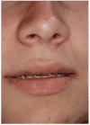
The amount of maxillary incisal show may vary with the patient's position. a. Incisor show at standing position b. Incisor show of the same subject at supine position
Fig 15
Fig 15
The amount of maxillary incisal show may vary with the patient's position. a. Incisor show at standing position b. Incisor show of the same subject at supine position

Similar articles

Cited by

References

    1. National Center for Health Statistics. National Hospital Discharge Survey: Annual Summary with Detailed Diagnosis and Procedure Data. Vital and Health Statistics series 13 number 151. DHHS publication No.(PHS)2001-1722. National Center for Health Statistics; Hyattsville, MD: 1999. - PubMed
    1. National Institutes of Health. Management of temporomandibular disorders. National Institutes of Health Technology Assessment Conference Statement. J Am Dent Assoc. 1996;127:1595. - PubMed
    1. National Center for Health Statistics. Third National Health and Nutrition Examination Survey, (NHANES III, 1988-1994) National Center for Health Statistics; Hyattsville, MD: 1996.
    1. Proffit WR, Fields HW, Jr, Moray LJ. Prevalence of malocclusion and orthodontic treatment need in the United States: estimates from the NHANES III survey. Int J Adult Orthodon Orthognath Surg. 1998;13:97. - PubMed
    1. Chatzis V, Pitas I. Interpolation of 3-D binary images based on morphologicalskeletonization. Medical Imaging, IEEE Transactions. 2000;19:699. - PubMed

MeSH terms