

Chemistry of personalized solar energy
- PMID: 19775081
- PMCID: PMC3332084
- DOI: 10.1021/ic901328v
Chemistry of personalized solar energy
Abstract
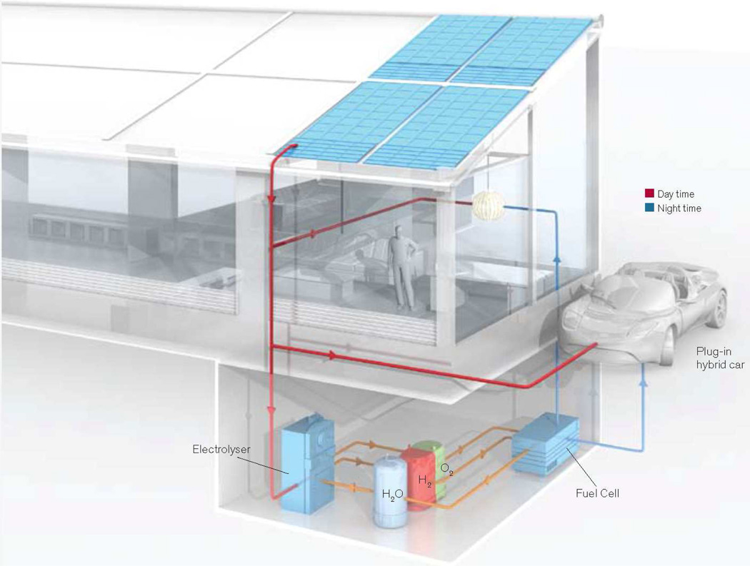
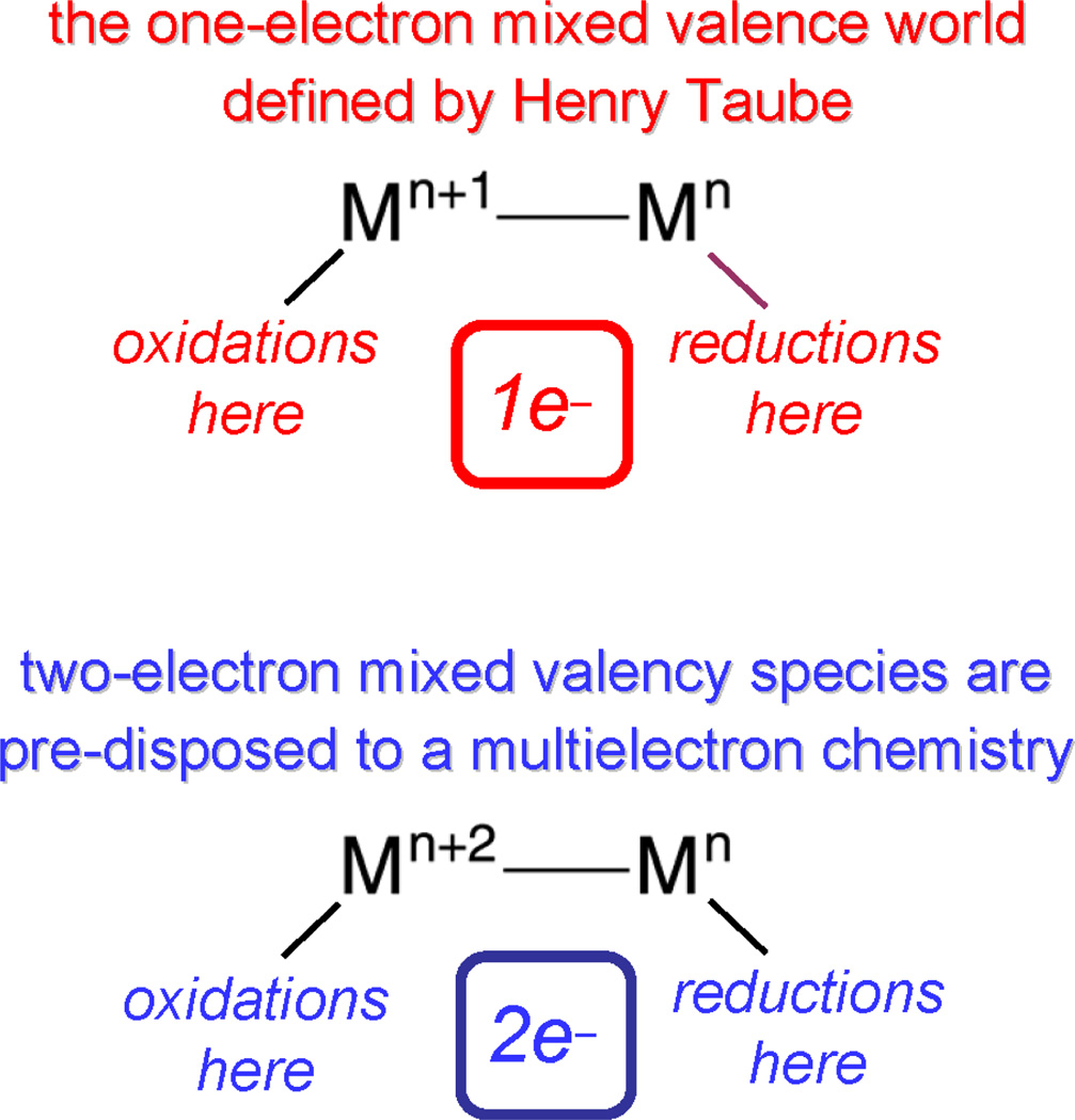
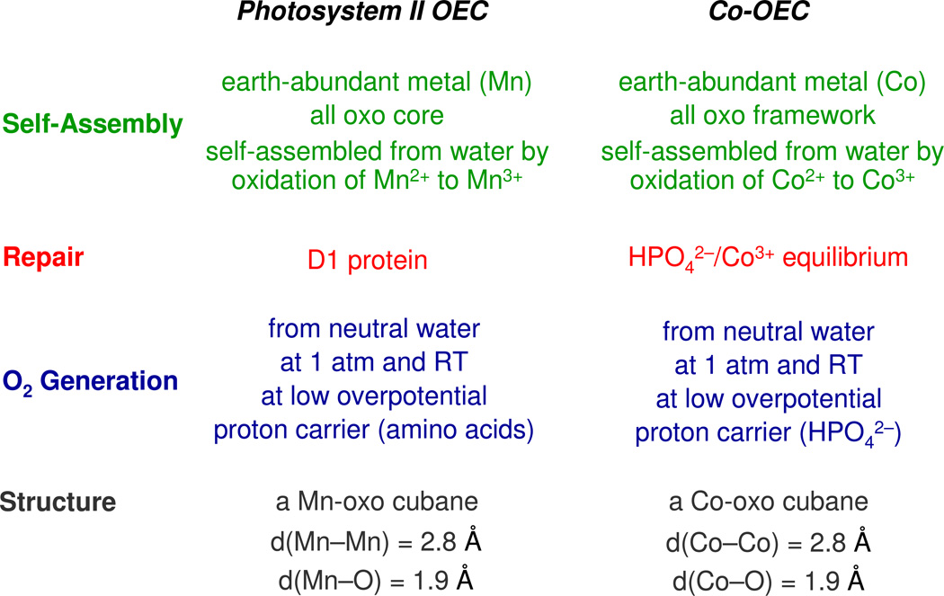
Personalized energy (PE) is a transformative idea that provides a new modality for the planet's energy future. By providing solar energy to the individual, an energy supply becomes secure and available to people of both legacy and nonlegacy worlds and minimally contributes to an increase in the anthropogenic level of carbon dioxide. Because PE will be possible only if solar energy is available 24 h a day, 7 days a week, the key enabler for solar PE is an inexpensive storage mechanism. HY (Y = halide or OH(-)) splitting is a fuel-forming reaction of sufficient energy density for large-scale solar storage, but the reaction relies on chemical transformations that are not understood at the most basic science level. Critical among these are multielectron transfers that are proton-coupled and involve the activation of bonds in energy-poor substrates. The chemistry of these three italicized areas is developed, and from this platform, discovery paths leading to new hydrohalic acid- and water-splitting catalysts are delineated. The latter water-splitting catalyst captures many of the functional elements of photosynthesis. In doing so, a highly manufacturable and inexpensive method for solar PE storage has been discovered.
Figures
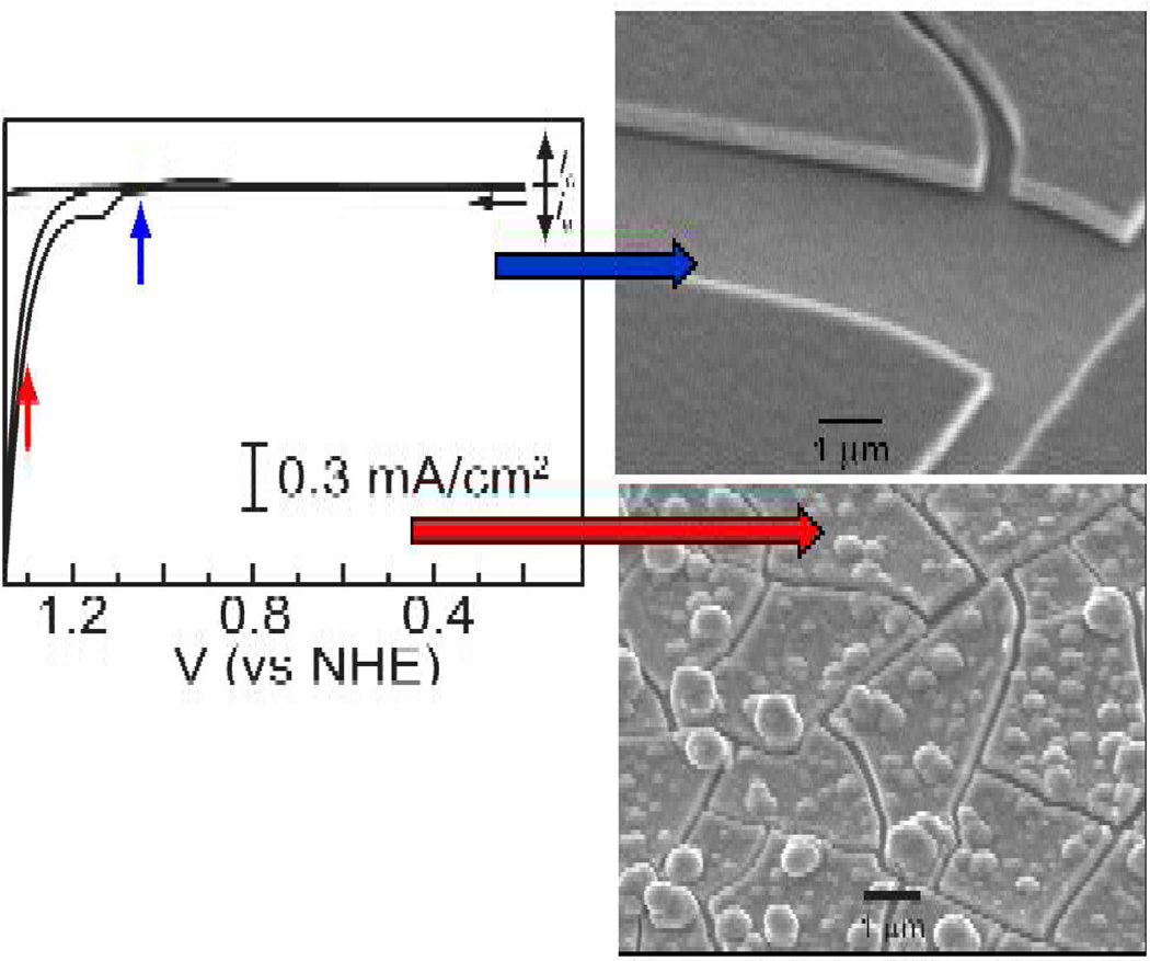
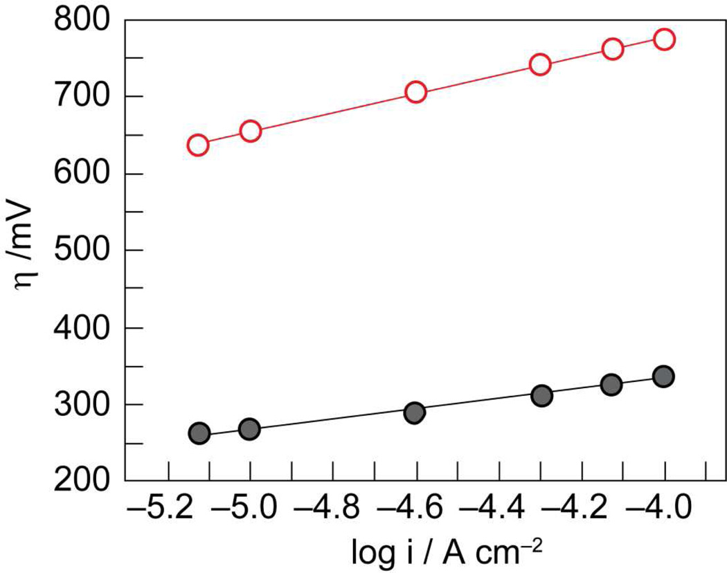
 , gray) at lower overpotentials relative to Pt (
 , red) in aqueous solutions containing phosphate.
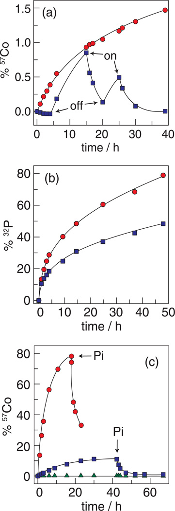
 ) (the trace begins with the applied potential on); and without an applied potential bias (
 ). (b) 32P leaching from Co-OEC on an electrode with an applied potential of 1.3 V (NHE) () and without an applied potential bias (). (c) Percentage of 57Co leached from a typical Co-oxide catalyst on an electrode under a potential bias of 1.3 V () and 1.5 V () (NHE) and an unbiased electrode (
 ). Pi was added at the time points indicated by the arrows. Figures adapted from ref. and reproduced here with permission from the American Chemical Society.
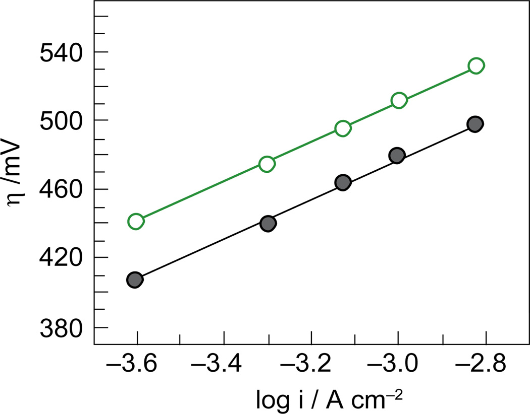 , gray) and water collected from the Charles River in front of MIT (
 , green).
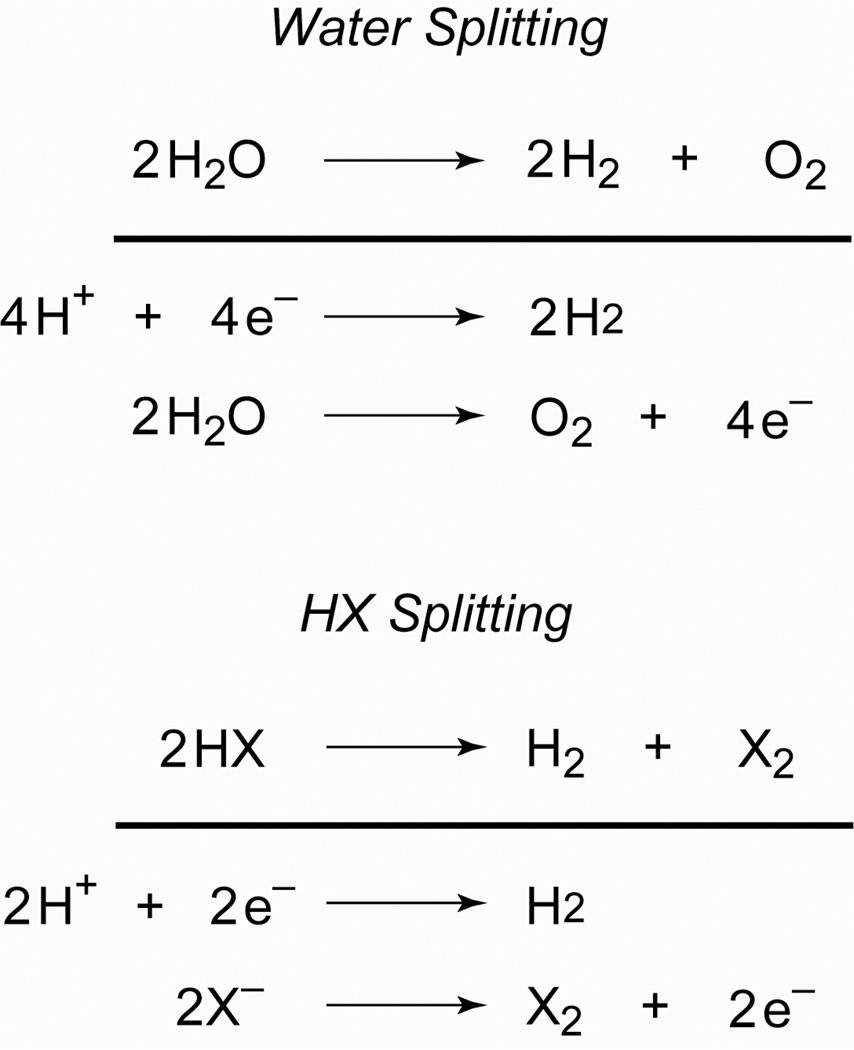
References
Publication types
MeSH terms
Substances
Grants and funding
LinkOut - more resources
Full Text Sources
Other Literature Sources
