

Reduction of the secondary neutron dose in passively scattered proton radiotherapy, using an optimized pre-collimator/collimator
- PMID: 19779218
- PMCID: PMC3688272
- DOI: 10.1088/0031-9155/54/20/003
Reduction of the secondary neutron dose in passively scattered proton radiotherapy, using an optimized pre-collimator/collimator
Abstract
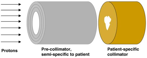
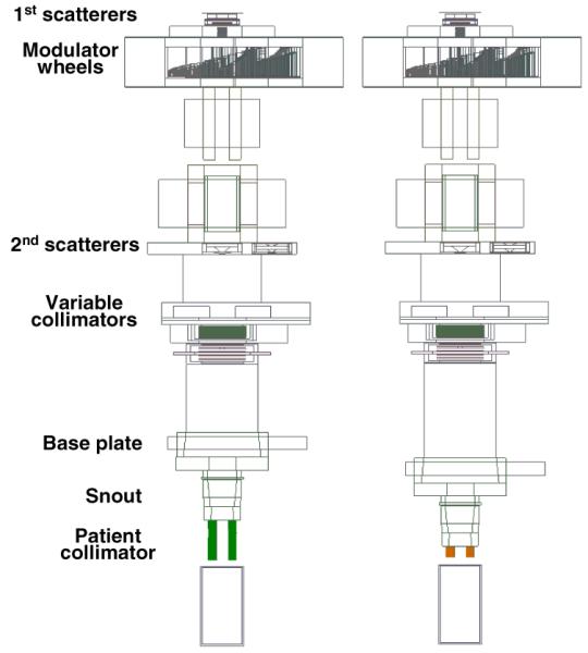
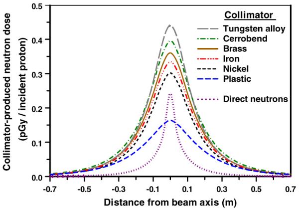
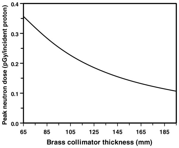
Proton radiotherapy represents a potential major advance in cancer therapy. Most current proton beams are spread out to cover the tumor using passive scattering and collimation, resulting in an extra whole-body high-energy neutron dose, primarily from proton interactions with the final collimator. There is considerable uncertainty as to the carcinogenic potential of low doses of high-energy neutrons, and thus we investigate whether this neutron dose can be significantly reduced without major modifications to passively scattered proton beam lines. Our goal is to optimize the design features of a patient-specific collimator or pre-collimator/collimator assembly. There are a number of often contradictory design features, in terms of geometry and material, involved in an optimal design. For example, plastic or hybrid plastic/metal collimators have a number of advantages. We quantify these design issues, and investigate the practical balances that can be achieved to significantly reduce the neutron dose without major alterations to the beamline design or function. Given that the majority of proton therapy treatments, at least for the next few years, will use passive scattering techniques, reducing the associated neutron-related risks by simple modifications of the collimator assembly design is a desirable goal.
Figures
Similar articles
-
Shielding design for a laser-accelerated proton therapy system.Phys Med Biol. 2007 Jul 7;52(13):3913-30. doi: 10.1088/0031-9155/52/13/017. Epub 2007 Jun 6. Phys Med Biol. 2007. PMID: 17664585
-
Monte Carlo investigation of collimator scatter of proton-therapy beams produced using the passive scattering method.Phys Med Biol. 2008 Jan 21;53(2):487-504. doi: 10.1088/0031-9155/53/2/014. Epub 2007 Dec 28. Phys Med Biol. 2008. PMID: 18185001
-
A Monte Carlo study of neutron contamination in presence of circular cones during stereotactic radiotherapy with 18 MV photon beams.Biomed Phys Eng Express. 2020 Apr 21;6(3):035016. doi: 10.1088/2057-1976/ab7ff2. Biomed Phys Eng Express. 2020. PMID: 33438661
-
Dosimetry of clinical neutron and proton beams: an overview of recommendations.Radiat Prot Dosimetry. 2004;110(1-4):565-72. doi: 10.1093/rpd/nch221. Radiat Prot Dosimetry. 2004. PMID: 15353710 Review.
-
Secondary neutrons in clinical proton radiotherapy: a charged issue.Radiother Oncol. 2008 Feb;86(2):165-70. doi: 10.1016/j.radonc.2007.12.003. Epub 2008 Jan 14. Radiother Oncol. 2008. PMID: 18192046 Review.
Cited by
-
Secondary neutron dose measurement for proton eye treatment using an eye snout with a borated neutron absorber.Radiat Oncol. 2013 Jul 17;8:182. doi: 10.1186/1748-717X-8-182. Radiat Oncol. 2013. PMID: 23866307 Free PMC article.
-
The physics of proton therapy.Phys Med Biol. 2015 Apr 21;60(8):R155-209. doi: 10.1088/0031-9155/60/8/R155. Epub 2015 Mar 24. Phys Med Biol. 2015. PMID: 25803097 Free PMC article. Review.
-
Proton versus photon-based radiation therapy for prostate cancer: emerging evidence and considerations in the era of value-based cancer care.Prostate Cancer Prostatic Dis. 2019 Dec;22(4):509-521. doi: 10.1038/s41391-019-0140-7. Epub 2019 Apr 9. Prostate Cancer Prostatic Dis. 2019. PMID: 30967625 Review.
-
Risk of second malignant neoplasm following proton versus intensity-modulated photon radiotherapies for hepatocellular carcinoma.Phys Med Biol. 2010 Dec 7;55(23):7055-65. doi: 10.1088/0031-9155/55/23/S07. Epub 2010 Nov 12. Phys Med Biol. 2010. PMID: 21076199 Free PMC article.
-
Proton beam therapy and localised prostate cancer: current status and controversies.Br J Cancer. 2013 Apr 2;108(6):1225-30. doi: 10.1038/bjc.2013.100. Epub 2013 Mar 12. Br J Cancer. 2013. PMID: 23481182 Free PMC article. Review.
References
-
- Agosteo S, Birattari C, Caravaggio M, Silari M, Tosi G. Secondary neutron and photon dose in proton therapy. Radiother. Oncol. 1998;48:293–3053. - PubMed
-
- Allison J. Facilities and methods: Geant4—a simulation toolkit. Nucl. Phys. News. 2007;17:20–4.
-
- Bagne F. Effects of collimator scattering on dose for a 45 MeV betatron. Phys. Med. Biol. 1974;19:236.
-
- Binns PJ, Hough JH. Secondary dose exposures during 200 MeV proton therapy. Radiat. Prot. Dosim. 1997;70:441–4.
-
- Bonnett DE, Kacperek A, Sheen MA, Goodall R, Saxton TE. The 62 MeV proton beam for the treatment of ocular melanoma at Clatterbridge. Br. J. Radiol. 1993;66:907–14. - PubMed
Publication types
MeSH terms
Substances
Grants and funding
LinkOut - more resources
Full Text Sources
Other Literature Sources
Medical