

Split gradient coils for simultaneous PET-MRI
- PMID: 19780167
- PMCID: PMC4304006
- DOI: 10.1002/mrm.22143
Split gradient coils for simultaneous PET-MRI
Abstract
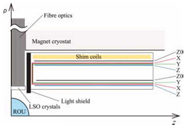
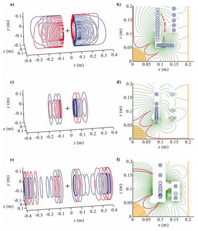
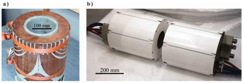
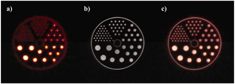
Combining positron emission tomography (PET) and MRI necessarily involves an engineering tradeoff as the equipment needed for the two modalities vies for the space closest to the region where the signals originate. In one recently described scanner configuration for simultaneous positron emission tomography-MRI, the positron emission tomography detection scintillating crystals reside in an 80-mm gap between the 2 halves of a 1-T split-magnet cryostat. A novel set of gradient and shim coils has been specially designed for this split MRI scanner to include an 110-mm gap from which wires are excluded so as not to interfere with positron detection. An inverse boundary element method was necessarily employed to design the three orthogonal, shielded gradient coils and shielded Z0 shim coil. The coils have been constructed and tested in the hybrid positron emission tomography-MRI system and successfully used in simultaneous positron emission tomography-MRI experiments.
(c) 2009 Wiley-Liss, Inc.
Figures
References
-
- Shaw NR, Ansorge RE, Carpenter TA. Proc Int Soc Magn Reson Med. Vol. 13. Miami Beach, Florida: 2005. Commissioning and testing of split coil MRI system for combined PET-MR; p. 407.
-
- Lucas AJ, Hawkes RC, Ansorge RE, Williams GB, Nutt RE, Clark JC, Fryer TD, Carpenter TA. Development of a Combined microPET-MR System. Technol Cancer Res Treatment. 2006;5:826–830. - PubMed
-
- Hawkes RC, Fryer TD, Lucas AJ, Siegel SB, Ansorge RE, Clark JC, Carpenter TA. Initial performance assessment of a combined microPET® focus-F120 and MR split magnet system. Nuclear Science Symposium Conference Record. 2008:3673–3678. NSS ’08. IEEE.
-
- Grazioso R, Ladebeck R, Schmand M, Krieg R. Proc Int Soc Magn Reson Med. Vol. 13. Miami Beach, Florida: 2005. APD-based PET for combined MR-PET imaging; p. 408.
-
- Pichler BJ, Judenhofer MS, Catana C, Walton JH, Kneilling M, Nutt RE, Siegel SB, Claussen CD, Cherry SR. Performance Test of an LSO-APD Detector in a 7-T MRI Scanner for Simultaneous PET/MRI. J Nucl Med. 2006;47:639–647. - PubMed
Publication types
MeSH terms
Grants and funding
LinkOut - more resources
Full Text Sources
Other Literature Sources
Medical
Miscellaneous
