

doi: 10.1103/PhysRevLett.103.128101.
Epub 2009 Sep 17.
Magnetic wire traps and programmable manipulation of biological cells
Affiliations
- PMID: 19792462
- PMCID: PMC3928075
- DOI: 10.1103/PhysRevLett.103.128101
Item in Clipboard
Magnetic wire traps and programmable manipulation of biological cells
Phys Rev Lett.
.
Abstract
We present a multiplex method, based on microscopic programmable magnetic traps in zigzag wires patterned on a platform, to simultaneously apply directed forces on multiple fluid-borne cells or biologically inert magnetic microparticles or nanoparticles. The gentle tunable forces do not produce damage and retain cell viability. The technique is demonstrated with T-lymphocyte cells remotely manipulated (by a joystick) along desired trajectories on a silicon surface with average speeds up to 20 microm/s.
Figures
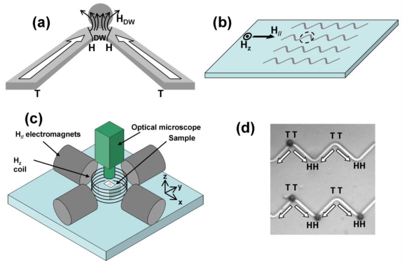
(a) Schematic of a rectangular zigzag wire with a head-to-head (HH) domain wall (DW) at the vertex, associated field HDW, and a trapped magnetic particle (gray circle). (b) Array of zigzag wires patterned on platform with perpendicular (Hz) and in-plane (H//) magnetic fields. Sketch in (a) is an enlarged view of the dotted circle around a vertex. (c) Schematic of electromagnets and coil to create H// and Hz. Cell movement observed by optical microscope (Reichert) with 20× objective lens and high speed camera. (d) Image of superparamagnetic spheres (2.8 μm diameter, dark circles) selectively attracted from solution and trapped only at HH and TT (tail-to-tail) domain walls under no external fields. The FeCo wires patterned on Si are 2 μm wide, 40 nm thick with 16 μm between adjacent vertices.
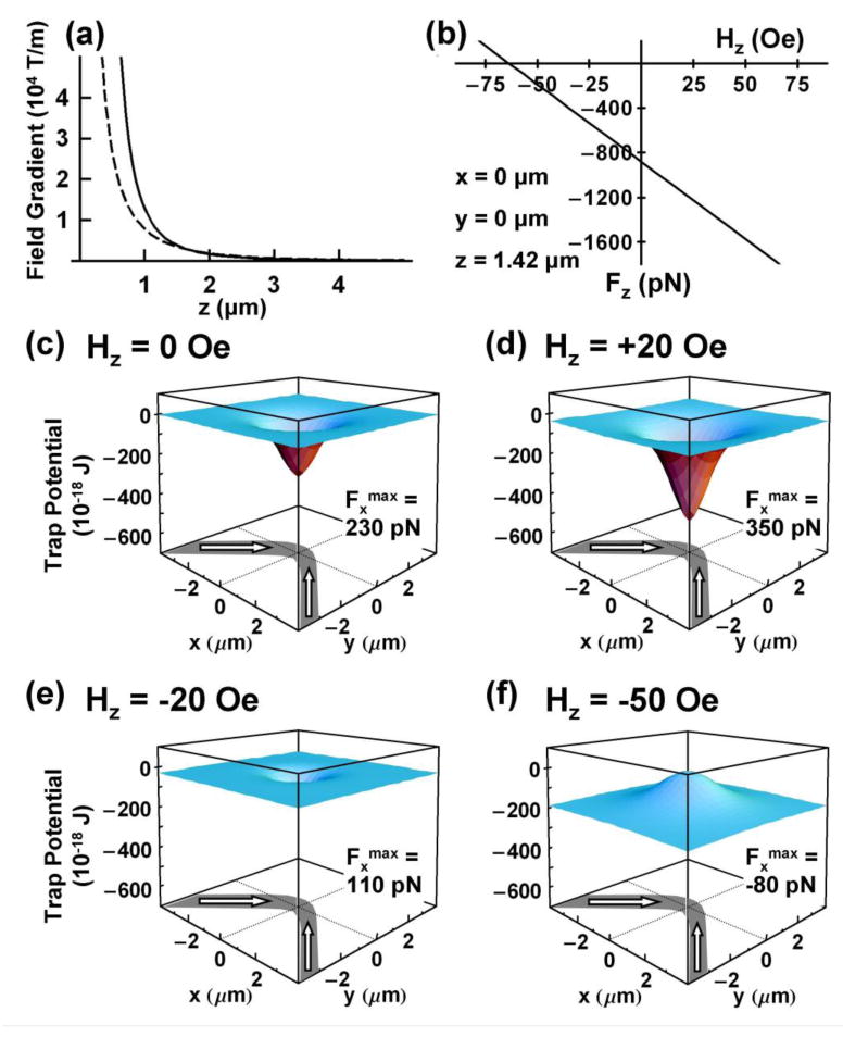
Calculated field gradient, force and energy profiles from a 1000 nm wide domain wall localized on a 40 nm thick, 1 μm wide FeCo wire. (a) Magnetic field gradients above the wire based on “point charge” (solid line) model and OOMMF simulations (dashed line) increase rapidly above 104 T/m as distance z to the domain wall decreases. (b) Variation of axial force Fz determined from “point charge' model on a magnetic bead (χ = 0.85) lying 1.42 μm above domain wall with external field Hz. (c)–(f) potential energy profiles transform from attractive (c, d, e) to repulsive (f) by changing Hz further negative. Calculated maximum force Fxmax along length of wire shows its tunability with Hz. Note for distances z >1300 nm relevant to this study, the magnetic energies are not sensitive to the precise magnetization profiles within the domain wall.
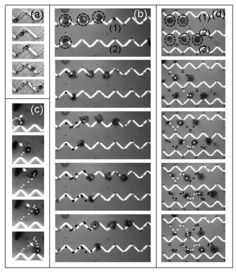
(a) Sequential applications of planar (H//) and perpendicular (HZ) fields transport (indicated by dots) a microsphere on a Si platform along a zigzag wire. (b) Transport of several T-lymphocyte cells along the wires. The cells (dashed circles in top panel) are conjugated to 1 μm magnetic spheres. (c) Trajectory (white dots) of a single T-lymphocyte cell away from the wires and its controlled return to a neighboring vertex on the same wire. The arrows (and dashed circle in first panel) identify the cell. (d) Simultaneous back and forth transport of five fluid borne T-cells between zigzag wire (1) (2) and (3). Dots identify trajectory of five cells.
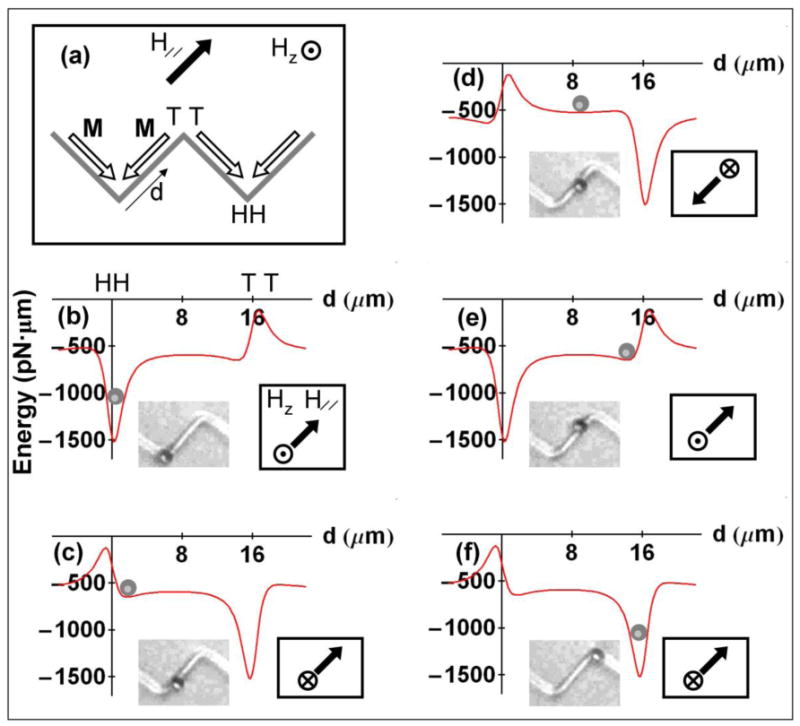
(a) Orientation of a zigzag wire, magnetization M (open arrows), and external H//, HZ fields. (b) – (f) Variation of magnetic potential energy within “point charge” model with distance d from the HH vertex along the wire. Orientations of H// and Hz are indicated. Inset photographs show close correlation between locations of a microsphere with a diameter of 2.8 μm on the wire and the calculated local energy minimum position.
Similar articles
-
Manipulation of magnetically labeled and unlabeled cells with mobile magnetic traps.Biophys J. 2010 Feb 3;98(3):412-7. doi: 10.1016/j.bpj.2009.10.036. Biophys J. 2010. PMID: 20141754 Free PMC article.
-
Contactless diamagnetic trapping of living cells onto a micromagnet array.Annu Int Conf IEEE Eng Med Biol Soc. 2008;2008:3360-3. doi: 10.1109/IEMBS.2008.4649926. Annu Int Conf IEEE Eng Med Biol Soc. 2008. PMID: 19163429
-
Regulating Brownian fluctuations with tunable microscopic magnetic traps.Phys Rev Lett. 2011 Aug 19;107(8):087206. doi: 10.1103/PhysRevLett.107.087206. Epub 2011 Aug 18. Phys Rev Lett. 2011. PMID: 21929204 Free PMC article.
-
The study of cells by optical trapping and manipulation of living cells using infrared laser beams.ASGSB Bull. 1991 Jul;4(2):133-46. ASGSB Bull. 1991. PMID: 11537176 Review.
-
Magnetic nanovectors for drug delivery.Nanomedicine. 2012 Sep;8 Suppl 1:S37-50. doi: 10.1016/j.nano.2012.05.010. Epub 2012 May 26. Nanomedicine. 2012. PMID: 22640907 Review.
Cited by
-
Assessing the Challenges of Nanotechnology-Driven Targeted Therapies: Development of Magnetically Directed Vectors for Targeted Cancer Therapies and Beyond.Methods Mol Biol. 2023;2575:105-123. doi: 10.1007/978-1-0716-2716-7_6. Methods Mol Biol. 2023. PMID: 36301473
-
Dynamic trajectory analysis of superparamagnetic beads driven by on-chip micromagnets.J Appl Phys. 2015 Nov 28;118(20):203904. doi: 10.1063/1.4936219. Epub 2015 Nov 24. J Appl Phys. 2015. PMID: 26648596 Free PMC article.
-
Thrust and Power Output of the Bacterial Flagellar Motor: A Micromagnetic Tweezers Approach.Biophys J. 2019 Oct 1;117(7):1250-1257. doi: 10.1016/j.bpj.2019.08.036. Epub 2019 Sep 6. Biophys J. 2019. PMID: 31540710 Free PMC article.
-
Real-time magnetic actuation of DNA nanodevices via modular integration with stiff micro-levers.Nat Commun. 2018 Apr 13;9(1):1446. doi: 10.1038/s41467-018-03601-5. Nat Commun. 2018. PMID: 29654315 Free PMC article.
-
Microfluidics cell sample preparation for analysis: Advances in efficient cell enrichment and precise single cell capture.Biomicrofluidics. 2017 Feb 6;11(1):011501. doi: 10.1063/1.4975666. eCollection 2017 Jan. Biomicrofluidics. 2017. PMID: 28217240 Free PMC article. Review.
References
Publication types
MeSH terms
Substances
Grants and funding
LinkOut - more resources
Full Text Sources
Other Literature Sources