. 2009 Nov 4;131(43):15903-8.
doi: 10.1021/ja906381y.

Multilayer DNA origami packed on a square lattice

Affiliations

Multilayer DNA origami packed on a square lattice

Yonggang Ke et al. J Am Chem Soc. .

Abstract

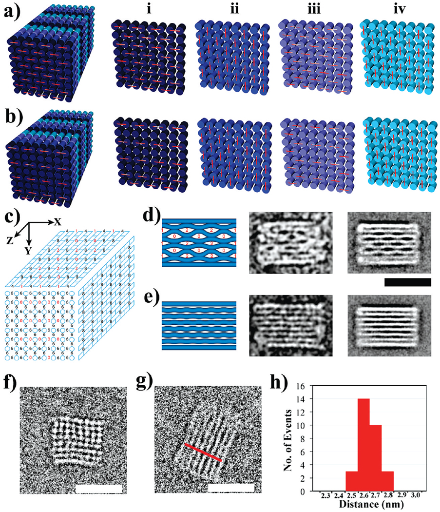
Molecular self-assembly using DNA as a structural building block has proven to be an efficient route to the construction of nanoscale objects and arrays of increasing complexity. Using the remarkable "scaffolded DNA origami" strategy, Rothemund demonstrated that a long single-stranded DNA from a viral genome (M13) can be folded into a variety of custom two-dimensional (2D) shapes using hundreds of short synthetic DNA molecules as staple strands. More recently, we generalized a strategy to build custom-shaped, three-dimensional (3D) objects formed as pleated layers of helices constrained to a honeycomb lattice, with precisely controlled dimensions ranging from 10 to 100 nm. Here we describe a more compact design for 3D origami, with layers of helices packed on a square lattice, that can be folded successfully into structures of designed dimensions in a one-step annealing process, despite the increased density of DNA helices. A square lattice provides a more natural framework for designing rectangular structures, the option for a more densely packed architecture, and the ability to create surfaces that are more flat than is possible with the honeycomb lattice. Thus enabling the design and construction of custom 3D shapes from helices packed on a square lattice provides a general foundational advance for increasing the versatility and scope of DNA nanotechnology.


Figures

Figure 1
Figure 1
Design of multilayer three-dimensional DNA origami on a square lattice. (a) Helical DNA model of the 3D origami square-lattice structure. The scaffold strand is in gray and the staple strands are in three shades of blue. This model is equivalent to the cylinder model shown on the right. Each cylindrical rod represents one DNA double helix. The numbers labeled at the helical ends indicate the order of the scaffold-strand segments that thread through the helices. (b) Layout and connectivity of the scaffold strand (gray) and the staple strands (colored), in an unfolded two-dimensional scheme of the target shape. Phosphate linkages that form crossovers between adjacent helices are shown as curved lines. The positions of the crossover points of the staple strands are labeled from i to iv, which are spaced apart at 8-bp intervals. (c) Three-dimensional cylinder model of the folded target shape. The square-lattice arrangement of parallel helices is revealed in cross-sectional slices (i–iv) that are parallel to the xy-plane spaced at 8-bp intervals and repeating every 32 bp. Staple crossovers are shown as white lines linking two adjacent helices at each cross section.
Figure 2
Figure 2
3D DNA origami solid blocks. (a) Two-layer structure. (b) Three-layer structure. (c) Six-layer structure. (d) Eight-layer structure. The 3D perspective cylinder view and the projections of the top view and the side view are shown. Each cylinder represents a DNA double helix. For the 8-layer block in d, the end-view projection is shown. On the right are the representative transmission electron microscope (TEM) micrographs of negatively stained particles observed. The scale bars are 20 nm. For imaging, samples were adsorbed for 30 s onto glow-discharged grids (carbon-coated grid, 400 mesh, Ted Pella) and stained with 0.7% uranyl formate. Excess stain was wicked away by touching with a piece of filter paper, then dried at room temperature. The samples were imaged with a Philips CM200 microscope, operated at 200 kV in the bright field mode.
Figure 3
Figure 3
Cryo-EM images of the 8 × 8 square lattice. (a) Three-dimensional cylinder model of a hypothetical 8 × 8 square lattice with all default staple crossovers intact. Cross-sectional slices i to iv (parallel to the xy-plane, spaced at 8-bp intervals) reveal that each slice retains 28 crossovers (short line in red), evenly distributed across the xy-plane. The crossovers in i and iii sectional slices are parallel to the xz-plane, while the crossovers in ii and iv sectional slices are parallel to the yz-plane. (b) 3D cylinder model of an 8 × 8 square lattice in which crossovers have been systematically omitted from i and iii sectional slices. This design decreases the density of crossovers parallel to the xz-plane. (c) Diagram illustrating the distribution of crossovers in the 8 × 8 square lattice along xy-, xz-, and yz-projections. As a result of the omissions of crossovers parallel to the xz-plane, the numbers of crossovers along lines parallel to the y-axis are significantly smaller at certain positions (number of crossovers indicated in red). (d) Left to right: predicted model of 8 × 8 square lattice in xz-projection; cryo-EM image of a single particle; and averaged image of 45 particles showing the side view corresponding to the xz-projection. (e) Left to right: predicted model of 8 × 8 square lattice in yz-projection; cryo-EM image of a single particle; and averaged image of 70 particles showing the side view coresponding to the yz-projection. (f) Cryo-EM image of a particle showing the end view corresponding to the xy-projection. (g) Cross-section analysis of the images gives the width of the construct from which the periodicity of the helices in the structure can be obtained. (h) Narrow distribution of helical widths centered at 2.6 nm. Scale bars in d–g: 20 nm.

References

    1. Tseng AA. Small. 2005;10:924–939. - PubMed
    1. Seeman NC. Nature (London, U. K.) 2003;421:427–431. - PubMed
    2. He Y, Ye T, Su M, Zhang C, Ribble AE, Jiang W, Mao C. Nature. 2008;452:198–201. - PubMed
    3. Zhang C, Su M, He Y, Zhao X, Fang P, Ribble AE, Jiang W, Mao C. Proc. Natl. Acad. Sci. U.S.A. 2008;105:10665–10669. - PMC - PubMed
    4. Shih WM, Quispe JD, Joyce GF. Nature. 2004;427:618–621. - PubMed
    5. Winfree E, Liu F, Wenzler LA, Seeman NC. Nature (London) 1998;394:539–544. - PubMed
    6. Aldaye FA, Sleiman HF. J. Am. Chem. Soc. 2009;129:13376–13377. - PubMed
    7. Fu TJ, Seeman NC. Biochemistry. 1993;32:3211–3220. - PubMed
    8. Li X, Yang X, Qi J, Seeman NC. J. Am. Chem. Soc. 1996;118:6131–6140.
    9. Rothemund PWK, Ekani-Nkodo A, Papadakis N, Kumar A, Fygenson DK, Winfree E. J. Am. Chem. Soc. 2004;126:16344–16352. - PubMed
    10. Mathieu F, Liao S, Kopatsch J, Wang T, Mao C, Seeman NC. Nano Lett. 2005;5:661–665. - PMC - PubMed
    11. Yin P, Hariadi RF, Sahu S, Choi HMT, Park SH, LaBean TH, Reif JH. Science. 2008;321:824–826. - PubMed
    12. Goodman RP, Schaap IAT, Tardin CF, Erben CM, Berry RM, Schmidt CF, Turberfield AJ. Science. 2005;310:1661–1665. - PubMed
    13. Chen J, Seeman NC. Nature (London) 1991;350:631–633. - PubMed
    14. Zhang Y, Seeman NC. J. Am. Chem. Soc. 1994;116:1661–1669.
    1. Yan H, Park SH, Finkelstein G, Reif JH, LaBean TH. Science. 2003;301:1882–1884. - PubMed
    1. Park SH, Yin P, Liu Y, Reif JH, LaBean TH, Yan H. Nano Lett. 2005;5:729–733. - PubMed
    1. Sharma J, Ke Y, Lin C, Chhabra R, Wang Q, Nangreave J, Liu Y, Yan H. Angew. Chem. 2008;47:5157–5159. - PMC - PubMed

Publication types

MeSH terms